Build a Workbench
The MPCNC router you will be using to mill components for replicating the experiment you are working on needs to be mounted to a workbench to maximize its rigidity and accuracy while milling. You will be building a workbench I designed for mounting the MPCNC and it contains a shelf at the bottom where the 3D Printer can be placed.
- Let’s Look at the Material Requirements
- Cutting the 4″x4″s and 2″x4″s to Length
- Let’s Look at the Finished Parts
- Drilling the 1/8″ Holes in the 2″x4″s
- Drilling the 3/8″ Counterbores in the 2″x4″s
- Applying Polyurethane and Melamine Edge Banding
- Assembling the Frame
- Install the Table Top
- Install the Shelf, Computer Station Drawer and Plugs
- Install the Computer Work Station
1. Let’s Look at the Material Requirements
2. Cutting the 4″x4″s and 2″x4″s to Length
To cut the 4″ x 4″s for the legs you will need a 12″ sliding compound miter saw. These can be rented from your local Home Depot or Lowes. If you are lucky a local Maker Space could have a tool library from which to check out such a tool for its members. I was able to take out such a saw from Makehaven, a local Maker space in New Haven, CT. I would recommend using the same saw for cutting all the 2″ x 4″s to length as well. A good saw will have a clamp that you can use to clamp the material to the fence before you turn the saw on and cut the piece. Below is a table with the recommended cuts of the two 4″x4″x96″ and eight 2″x4″x96″ pieces of wood.
| 4″x4″x96″ | 42″ | 42″ | ||
| 4″x4″x96″ | 42″ | 42″ | ||
| 2″x4″x96″ | 48″ | 42″ | 4.5″ | |
| 2″x4″x96″ | 48″ | 42″ | 4.5″ | |
| 2″x4″x96″ | 33″ | 33″ | 23″ | 4.5″ |
| 2″x4″x96″ | 33″ | 33″ | 23″ | 4.5″ |
| 2″x4″x96″ | 38.5″ | 38.5″ | ||
| 2″x4″x96″ | 38.5″ | 38.5″ | ||
| 2″x4″x96″ | 36″ | 36″ | 3″ Scrap | |
| 2″x4″x96″ | 26″ | 26″ | ||
For cutting the plywood I would recommend having your local home improvement store where you buy it cut the pieces to size for you.
| 48″x96″x0.75″ | 48″x36″ | 45″x26″ | 35.5″x24″ | 36″x4″ | 36″x4″ |
3. Let’s Look at the Finished Parts
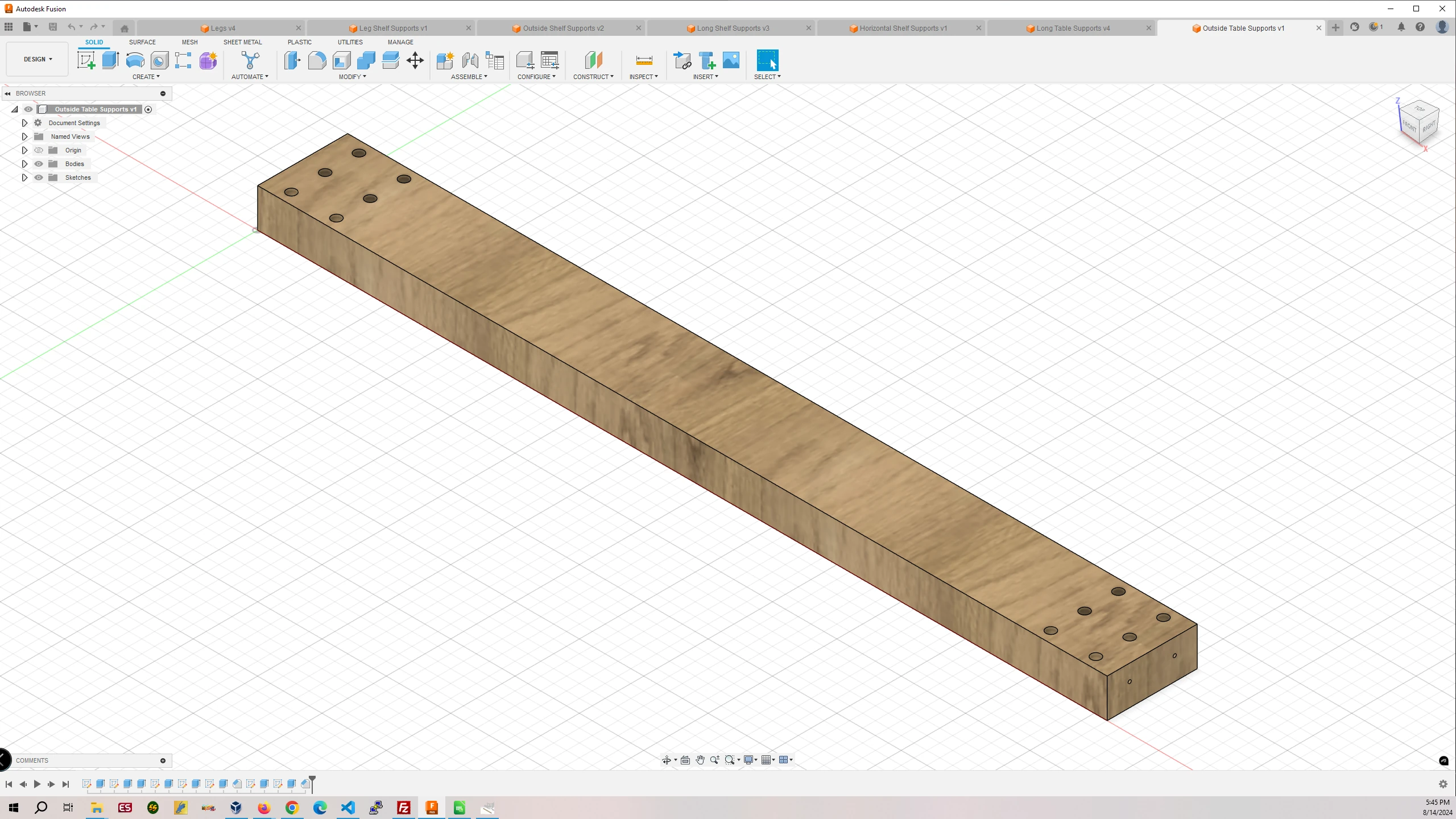
Part #1 Horizontal Leg Attached Table Supports
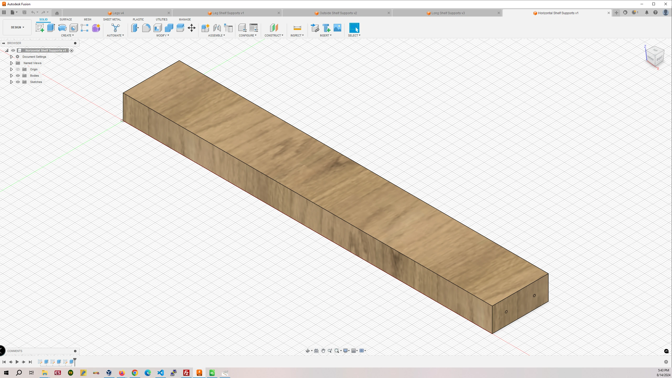
Part #2 Horizontal Shelf Supports
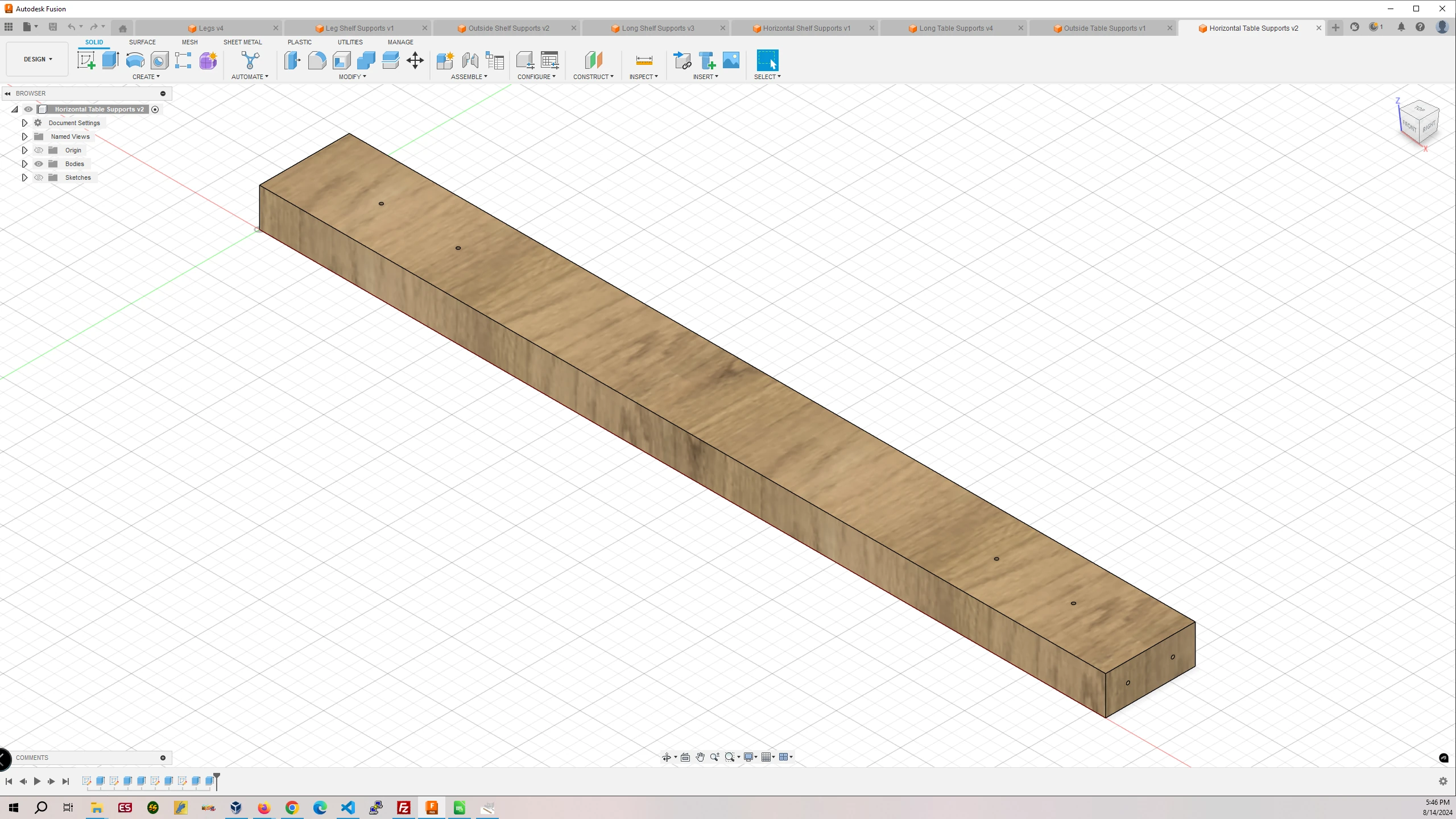
Part #3 Horizontal Table Supports
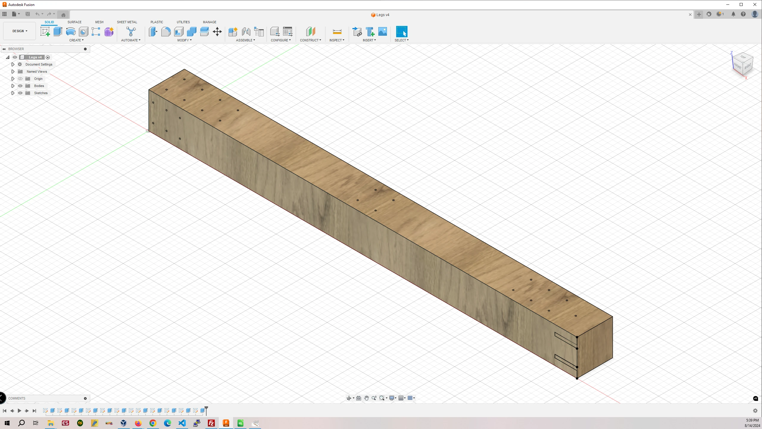
Part #4 Legs
Part #5 Leg Shelf Supports
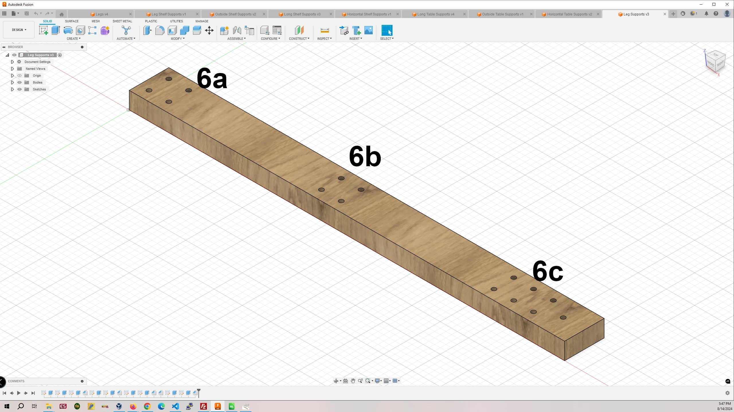
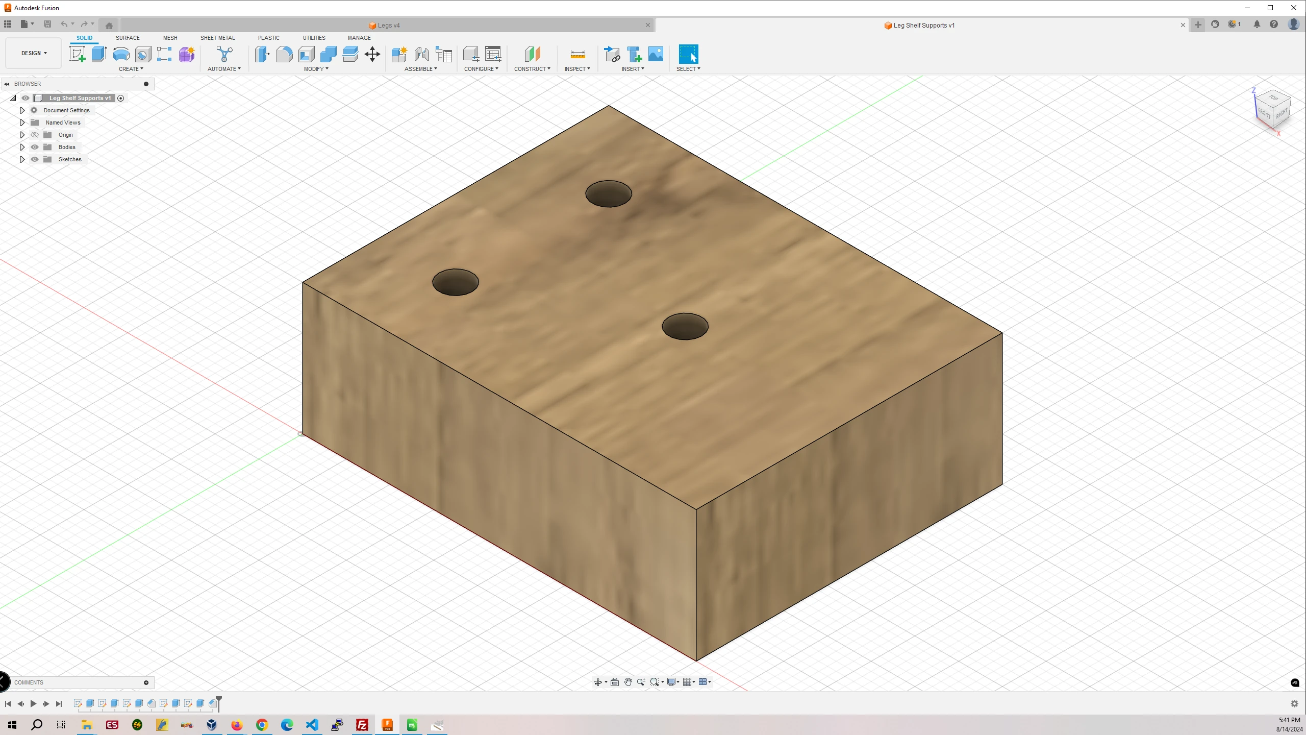
Part #6 Leg Supports
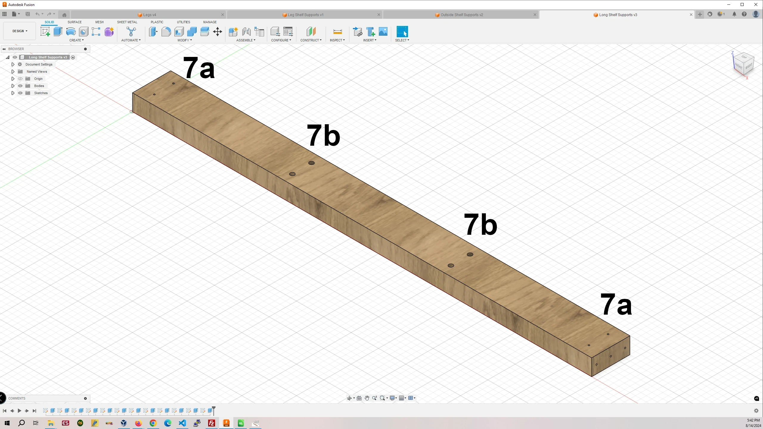
Part #7 Long Shelf Supports
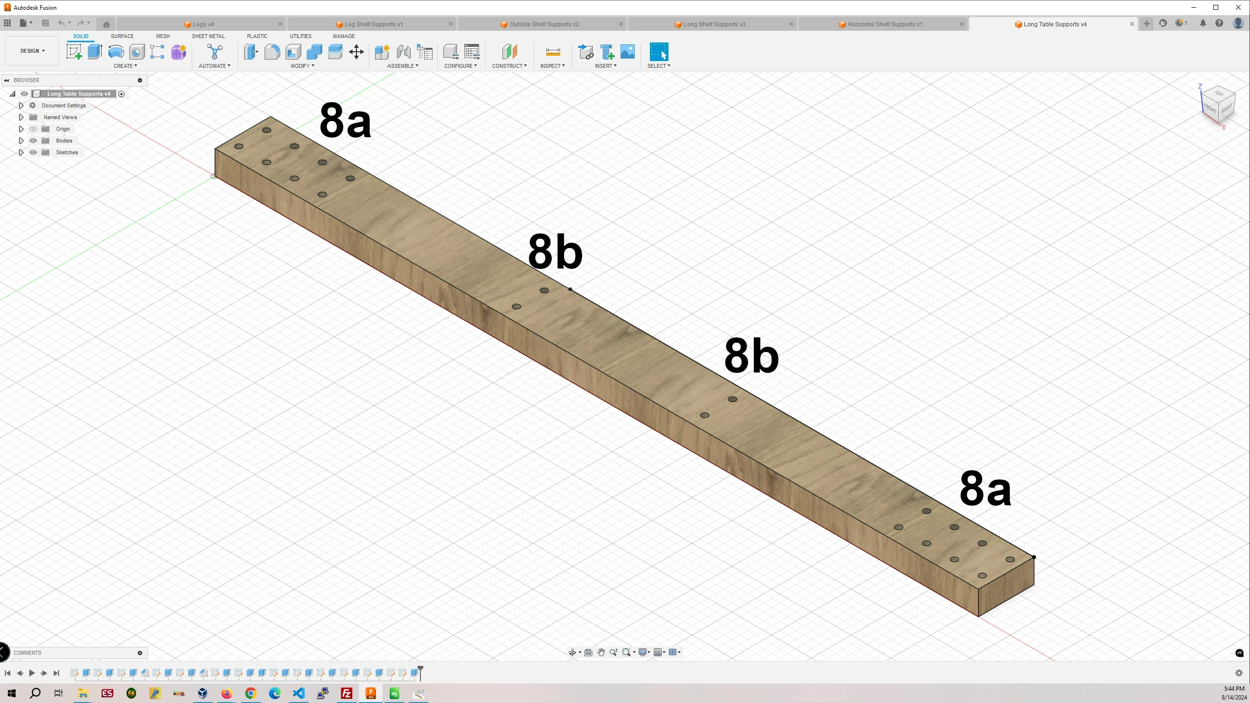
Part #8 Long Table Supports
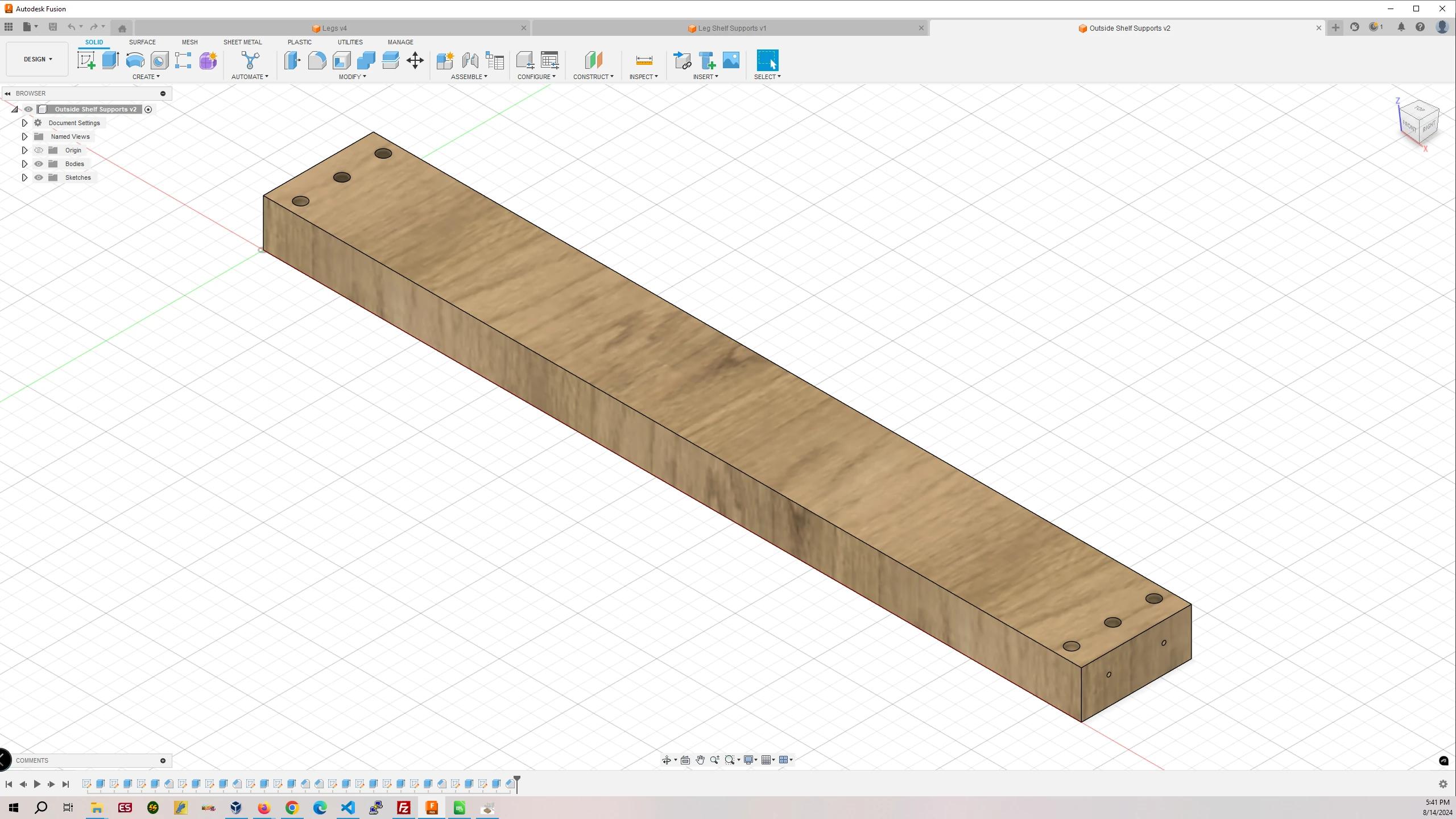
Part #9 Outside Shelf Supports
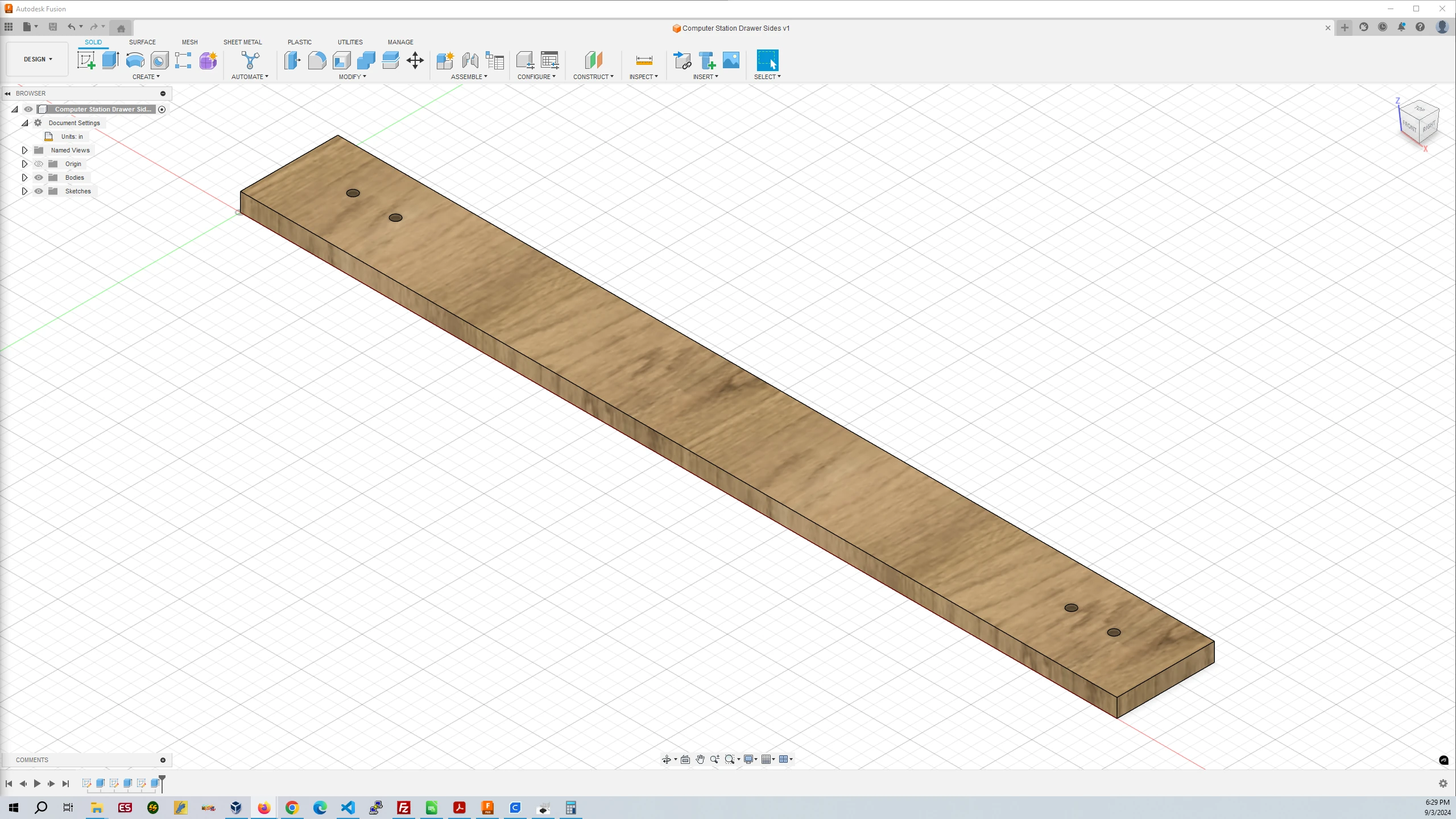
Part #13 Computer Station Drawer Sides
| Part # | Finished Part Name | Finished Part Size | Quantity |
|---|---|---|---|
| 1 | Horizontal Leg Attached Table Supports | 1.5″ x 3.5″ x 33″ | 4 |
| 2 | Horizontal Shelf Supports | 1.5″ x 3.5″ x 23″ | 2 |
| 3 | Horizontal Table Supports | 1.5″ x 3.5″ x 33″ | 2 |
| 4 | Legs | 3.5″ x 3.5″ x 42″ | 4 |
| 5 | Leg Shelf Supports | 1.5″ x 3.5″ x 4.5″ | 4 |
| 6 | Leg Supports | 1.5″ x 3.5″ x 38.5″ | 4 |
| 7 | Long Shelf Supports | 1.5″ x 3.5″ x 42″ | 2 |
| 8 | Long Table Supports | 1.5″ x 3.5″ x 48″ | 2 |
| 9 | Outside Shelf Supports | 1.5″ x 3.5″ x 26″ | 2 |
| 10 | Plywood Table Top | 48″ x 36″ x 0.75″ | 1 |
| 11 | Plywood Shelf Top | 45″ x 26″ x 0.75″ | 1 |
| 12 | Computer Station Drawer | 35.5″ x 24″ x 0.75″ | 1 |
| 13 | Computer Station Drawer Sides | 36″ x 4″ x 0.75″ | 2 |
| 14 | Leg Levelers | 8 | |
4. Drilling the 1/8″ Holes in the 4″x4″s, 2″x4″s, and Plywood
For drilling the holes accurately in the 4″x4″ and 2″x4″ pieces I have created three 3D printed drill hole templates that fit over the 4″x4″ and 2″x4″ pieces for drilling the 1/8″ holes in the correct locations. The templates have the part numbers next to the holes that match the part numbers in the images and table above. After those holes are drilled th holes in the 2″x4″s will be partially enlarged with a 3/8″ counterbore bit with 1/8″ guide bit for countersinking the screws used and capping the holes with 3/8″ hole plugs. I encourage the use of a double sided tape like Heavy Duty Acrylic Foam Mounting Tape applied to the templates to hold them to the 4″x4″s and 2″x4″s when drilling the holes. They will prevent the templates from moving and increasing the accuracy of the holes.
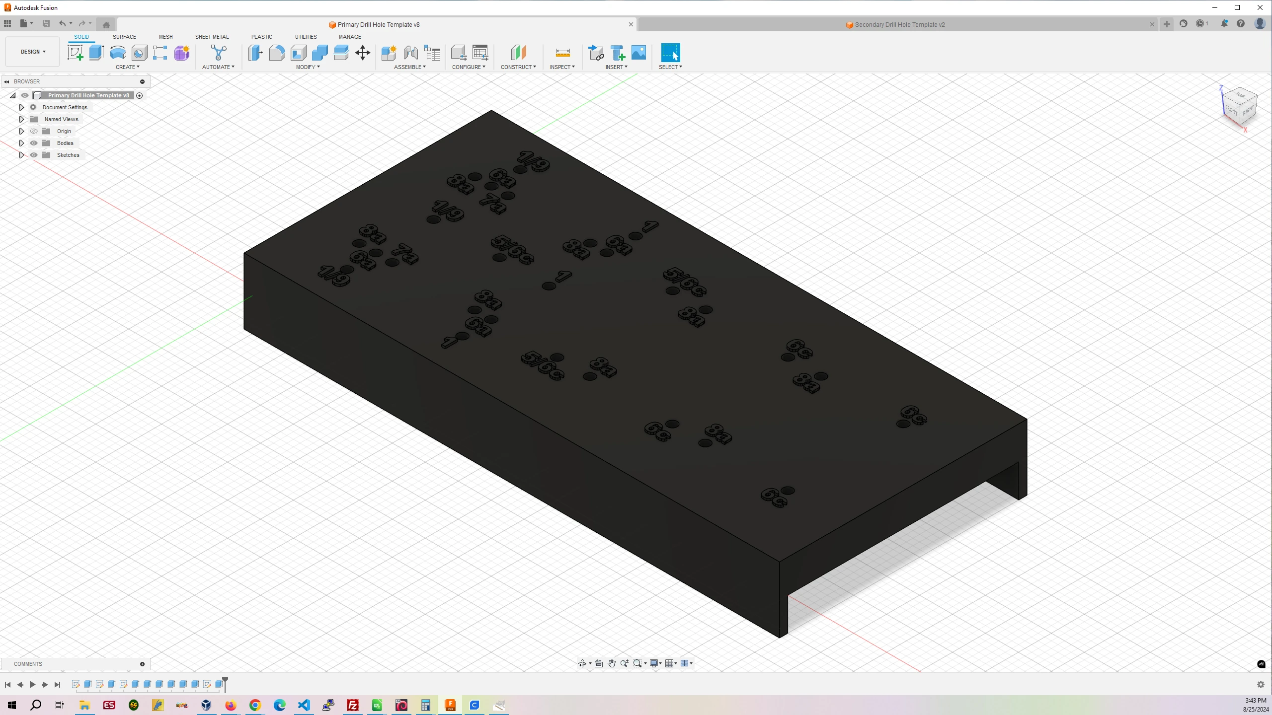
Drill Hole Template #1
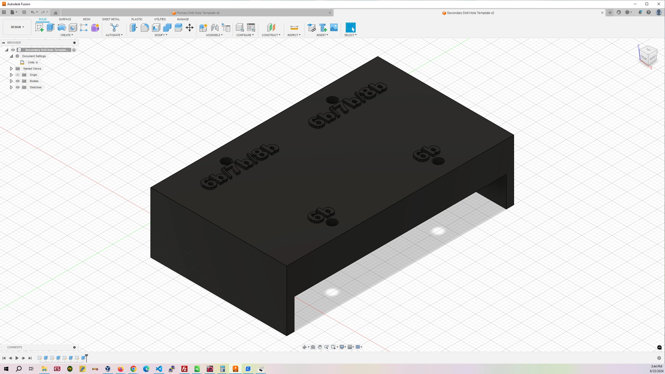
Drill Hole Template #2
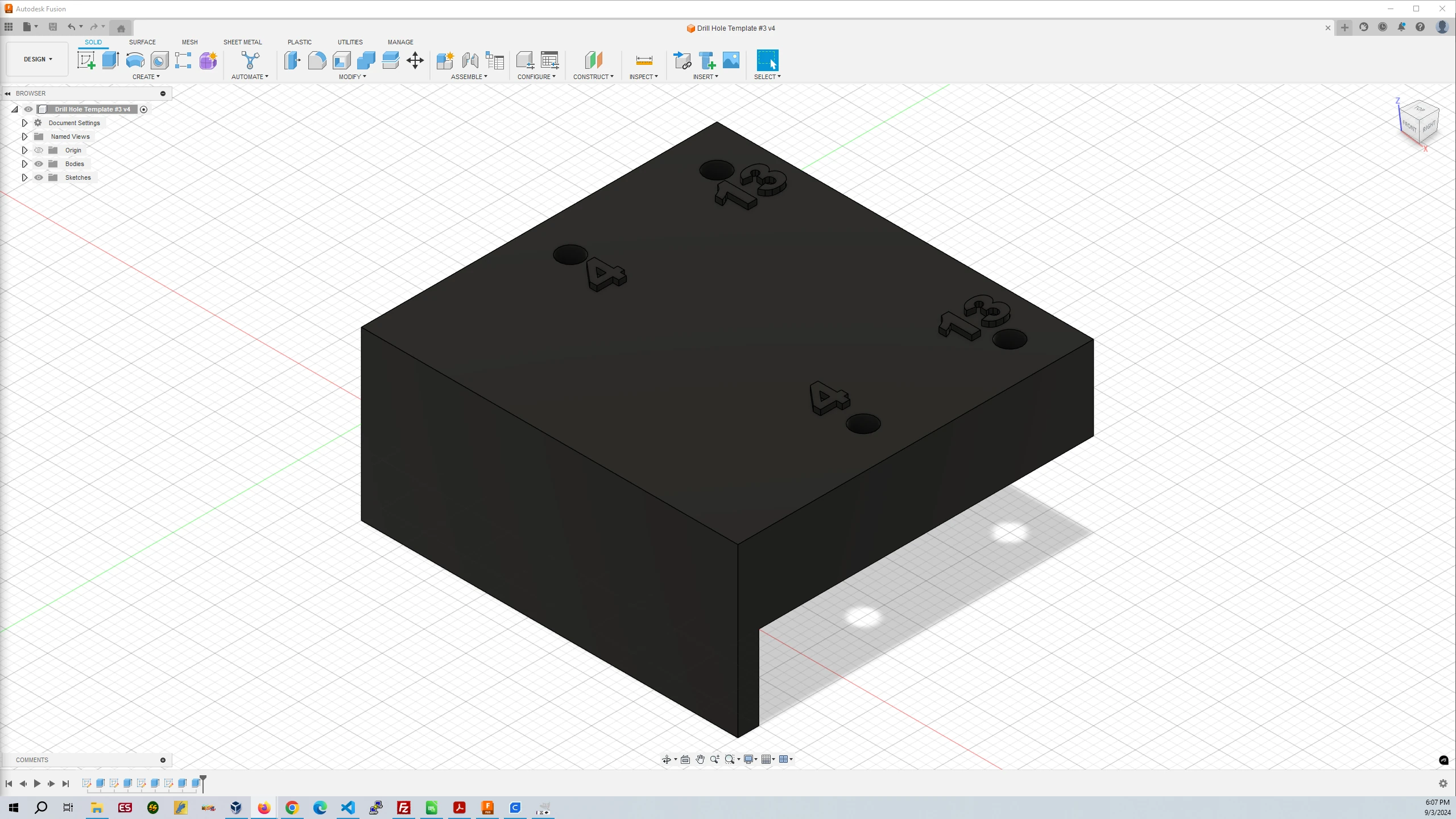
Drill Hole Template #3
Drill Hole Template #1
Filament Used: 166g – 55.66m
Time to Print: 8 hours 15 minutes
- Ultimaker Cura Settings
-
- Walls > Wall Thickness > 2.0 mm
- Infill > Infill Density > 5.0%
- Support > Generate Support > Checked
- Support > Support Structure > Tree
- Support > Support Placement > Everywhere
Drill Hole Template #2
Filament Used: 49g – 16.29m
Time to Print: 2 hours 24 minutes
- Ultimaker Cura Settings
-
- Walls > Wall Thickness > 2.0 mm
- Infill > Infill Density > 5.0%
- Support > Generate Support > Checked
- Support > Support Structure > Tree
- Support > Support Placement > Everywhere
Drill Hole Template #3
Filament Used: 24g – 7.97m
Time to Print: 1 hours 41 minutes
- Ultimaker Cura Settings
-
- Walls > Wall Thickness > 2.0 mm
- Infill > Infill Density > 5.0%
- Support > Generate Support > Checked
- Support > Support Structure > Tree
- Support > Support Placement > Everywhere
Print the drill hole templates vertically as they are oriented, don’t rotate them. If you are using a Creailty Ender 3 V3 SE printer then simply upload the .gcode files in the zip files via Octopi and print them. If you are using a different 3D printer, then open the .stl files in Ultimaker Cura, adjust the settings as written above, Slice the templates and print the resulting .gcode files.
The Drill Hole Templates are used for drilling 1/8″ holes in the lumber with the number codes on the templates matching the number codes in Step 3 in the image carousel and table.
Drill Hole Template #1 is used for holes that are near the ends of the 2″x4″s.
Drill Hole Template #2 is used for holes that are in the middle of 2″x4″s rather than at the ends. I definitely recommend applying a double sided tape like Heavy Duty Acrylic Foam Mounting Tape to the template to hold it in place on the 2″x4″s when drilling as Drill Hole Template #2 does not fit to the end of a 2″x4″ like Drill Hole Template #1 does.
In Part #6 – Measure from the top end of the board where four drill holes are located 15 7/8″ down and mark a line with your pencil. Then align Drill Hole Template #2 top with that line. Then proceed to drill the four 6b holes on the template.
In Part #7 – Measure from one end of the board 13 1/2″ down and mark a line with your pencil. Then align Drill Hole Template #2 side with the 7b holes with that line. Then proceed to drill the two 7b holes on the template. Then measure from the other end of the board 13 1/2″ down and mark a line with your pencil. Then align Drill Hole Template #2 side with the 7b holes with that line. Then proceed to drill the two 7b holes on the template.
In Part #8 – Measure from one end of the board 17 7/8″ down and mark a line with your pencil. Then align Drill Hole Template #2 side with the 8b holes with that line. Then proceed to drill the two 8b holes on the template. Then measure from the other end of the board 17 7/8″ down and mark a line with your pencil. Then align Drill Hole Template #2 side with the 8b holes with that line. Then proceed to drill the two 8b holes on the template.
Drill Hole Template #3 is used for drilling two holes on each leg and drilling the four holes in each Computer Station Drawer Side.
In Part #4 – Measure from the bottom end of the leg 5 1/8″ and mark a line with your pencil. Then align the Drill Hole Template top with that line on the outside edge of the leg. Then proceed to drill the two holes on the template. Do this for each leg. You should have two legs with holes on the left side and two with holes on the right side. These pilot holes are there because #9 5″ screws will be screwed in from the holes in the Leg Supports through the Legs and into the Outside Shelf Supports in Step 6c.
In Part #13 – Measure from the left edge 2 1/8″ and mark a line with your pencil. The align the template with the #13 holes on the bottom and the wood guide against the top of the plywood strip. Then proceed to drill the two holes on the template. Do this for the right edge of the board and for the other Computer Station Drawer Side as well.
5. Drilling the 3/8″ Counterbores in the 2″x4″s
All holes drilled with the templates need to be counterbored in order to countersink the screws and then cap the holes with plastic caps. You can’t see it in the image above but in Part #7, the 7a drill holes you drilled on the ends need to be counterbored from the back side of the lumber with the 7b drill holes counterbored on the front side of the lumber as shown. A good drill bit to use for this is a counterbore with a 1/8″ guide bit in the center like the one linked to at the top of the page. Using this bit you can ensure that the drill holes are centered in the counterbore holes. Drill the counterbores between 1/2″ and 3/4″ into the 2″x4″s.
6. Applying Polyurethane and Melamine Edge Banding
This step is optional and up to you. If your workbench is going to be in an area with moisture or water issues then I would advise applying two coats of polyurethane to each finished part. This will protect the wood from water damage. Apply the first coat to a part, wait for it to dry and apply the second coat. You can lightly sand the pieces after the first coat if you wish. Do this before assembly.
Applying the melamine edge banding is also optional. It will make the edges of the plywood look nice covering up the multiple layers of glued plywood. Use a heat gun to warm the banding and melt the glue. Then apply the banding the piece. When the banding is cool, use a razor blade to trim off the excess banding. One method to do this is to lay the front and back side of the razor blade flat against the edge of the piece of wood tilting the razor blade at a 45 degree angle against that edge. Then pull the razor blade to you to trim the excess banding.
7. Assembling the Frame
Assembling the frame of the workbench happens in several stages. First is to assemble the legs (Part #4), leg shelf supports (Part #5), and leg supports (Part #6). Second is to attach the long shelf supports (Part #7) and long table supports (Part #8) to the leg objects. Third is to attach the horizontal leg attached table supports (Part #1) and the outside shelf supports (Part #9). Fourth is to attach the horizontal shelf supports (Part #2) and horizontal table supports (Part #3).
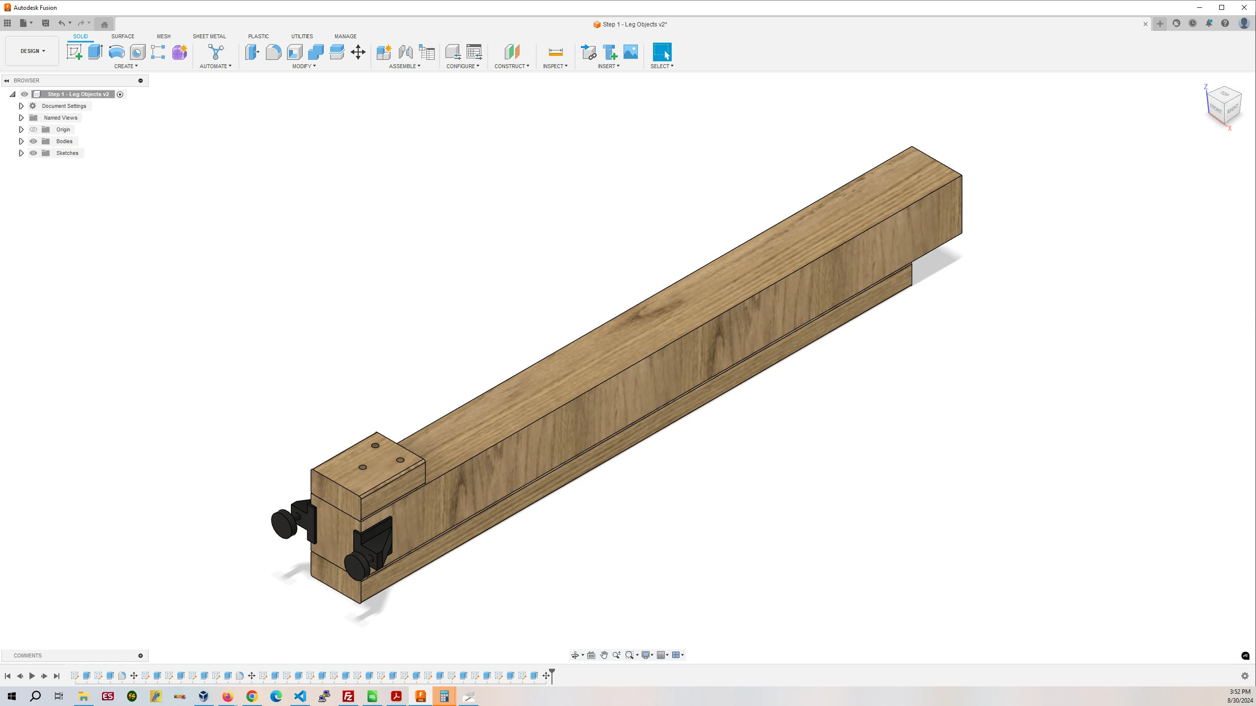
7a. Assembling the Legs
Use the scrap piece of wood left over from Step 2 placing it against the bottom of the 4″x4″ leg. Then place the leg shelf support against the 4″x4″ with its bottom edge against the scrap piece. Then use a squeeze clamp to secure the leg shelf support against the leg. Then screw the leg shelf support to the leg. Repeat this for all four legs.
Flip the leg over and use the scrap piece of wood left over from Step 2 placing it against the bottom of the 4″x4″ leg. Then place the leg support against the 4″x4″ with its bottom edge against the scrap piece. Then use two squeeze clamps to secure the leg support against the leg, one near the bottom and one near the top. Then screw the leg support to the leg. Repeat this for all four legs.
Next, attach the leg levelers. Use one leg leveler on each side of the leg as shown. When you screw the leg leveler to the 4″x4″ angle the screws up. This will pull the bottom lip of the leg leveler to the bottom of the 4″x4″ so the 4″x4″ will rest on the metal lip instead of being supported by just the screws.
You are now done assembling the legs.
Front
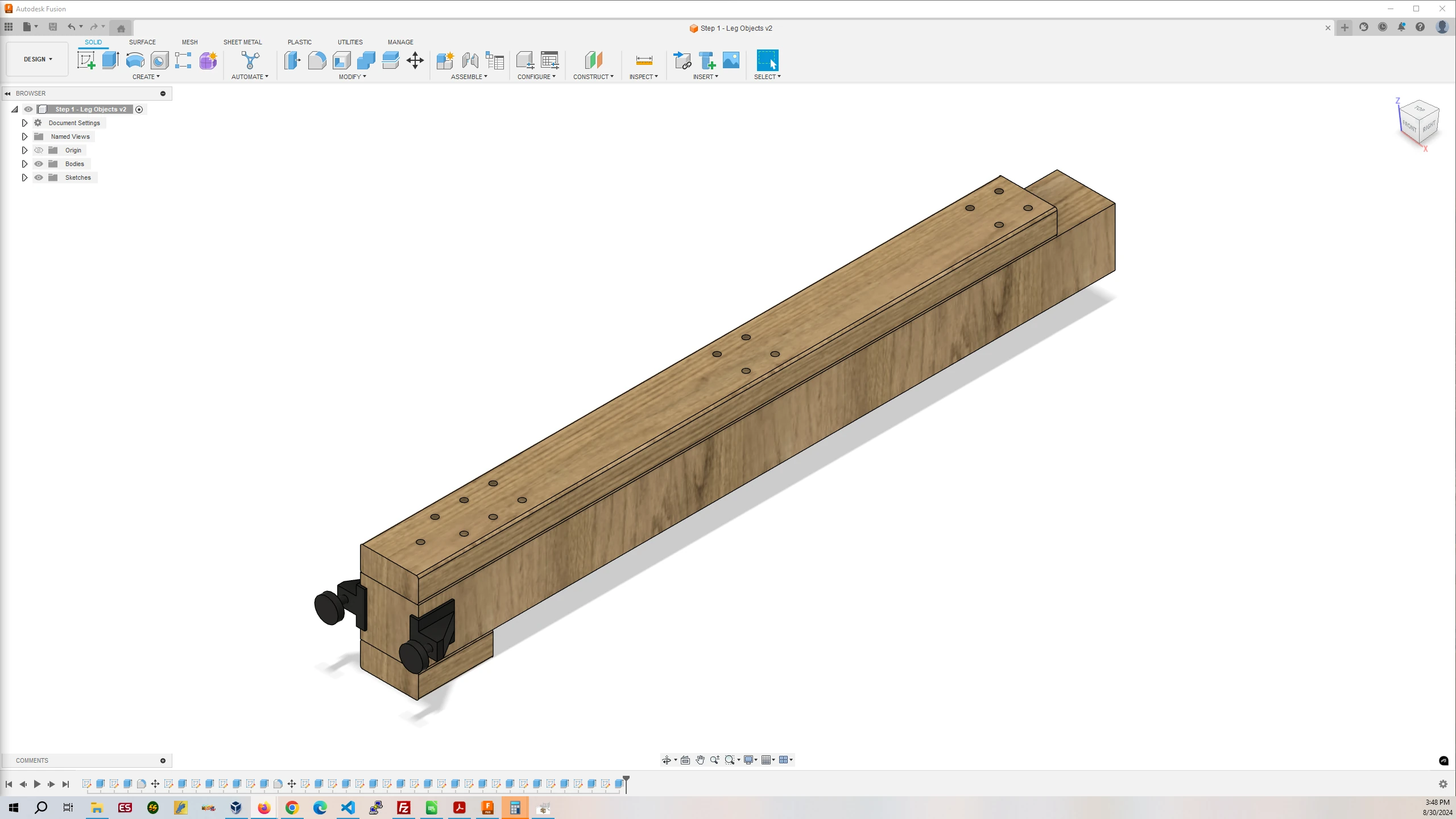
Back
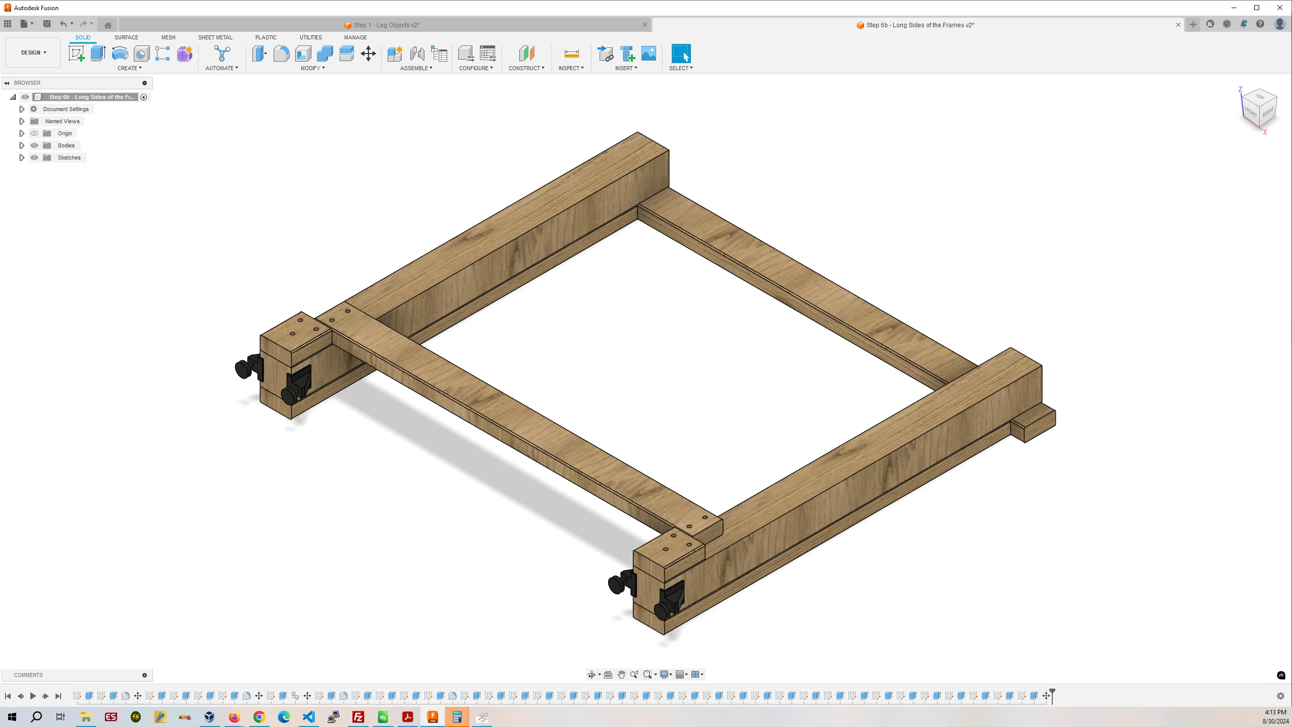
7b. Assembling the Long Sides of the Frame
Flip two legs over so the leg support sides are on the ground. Place the long shelf support on the back of the legs against the leg shelf supports. Place the piece of scrap on the leg against the leg shelf support on the outside edge of the leg. Use the piece of scrap to ensure there is 1.5″ spacing on each side of the long shelf support that is on the leg against the leg shelf support. This will ensure the proper spacing for the outside shelf supports in 6c. Use the squeeze clamps to secure the long shelf support to the two legs and screw them together. Repeats this for the other long side of the frame.
Then, flip two legs over so the leg supports are up. Place the long table support on the two legs against the leg supports while using the scrap to ensure the long table support overhangs the legs by the thickness of a 2″x4″ on each side. Use the squeeze clamps to secure the long table support to the legs and screw them together. Repeat this for the other long side of the frame.
You are now done assembling the long sides of the workbench frame.
Front
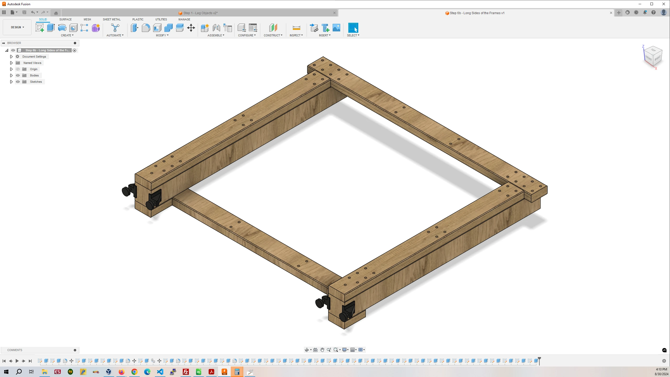
Back
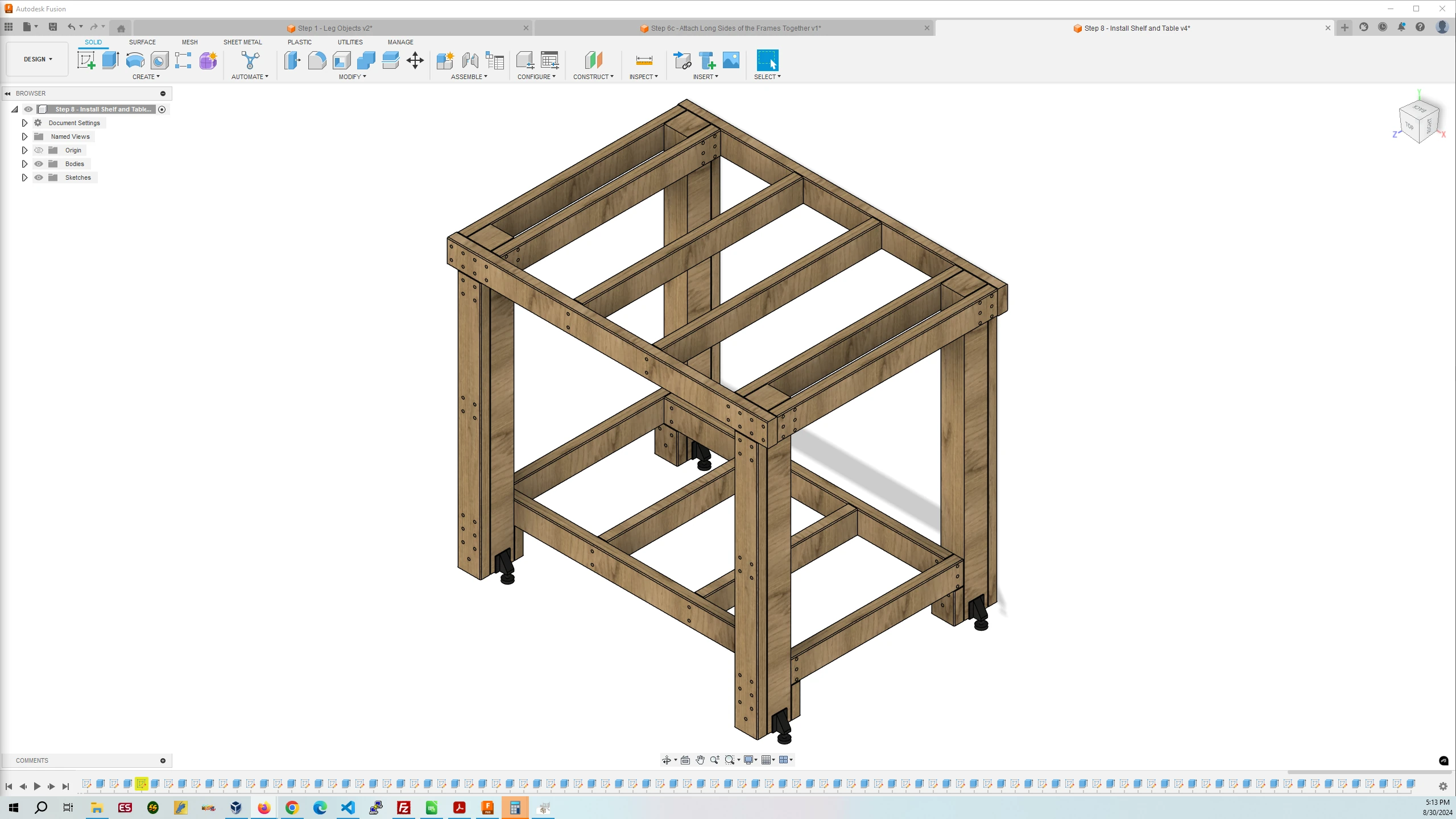
7c. Attaching the Two Long Side Frames Together
The easiest method for attaching the two 4ft long sides together is two attach the Horizontal Leg Attached Table Supports to one side first using the squeeze clamps to hold each piece to the frame while screwing them together. Repeat this for all four Horizontal Leg Attached Table Supports.
After this is done proceed to place the other ends of the Horizontal Leg Attached Table Supports against their cooresponding spots on the other frame. Make sure to place the Outside Shelf Supports at the bottom in place as well before screwing the other frame to the ends of the supports. Try to get everying as accurately lined up as possible and clamp the pieces together that your are fastening.
If wouldn’t hurt to use a square or level while doing this if you have them.
You are now done assembling the long frames together.
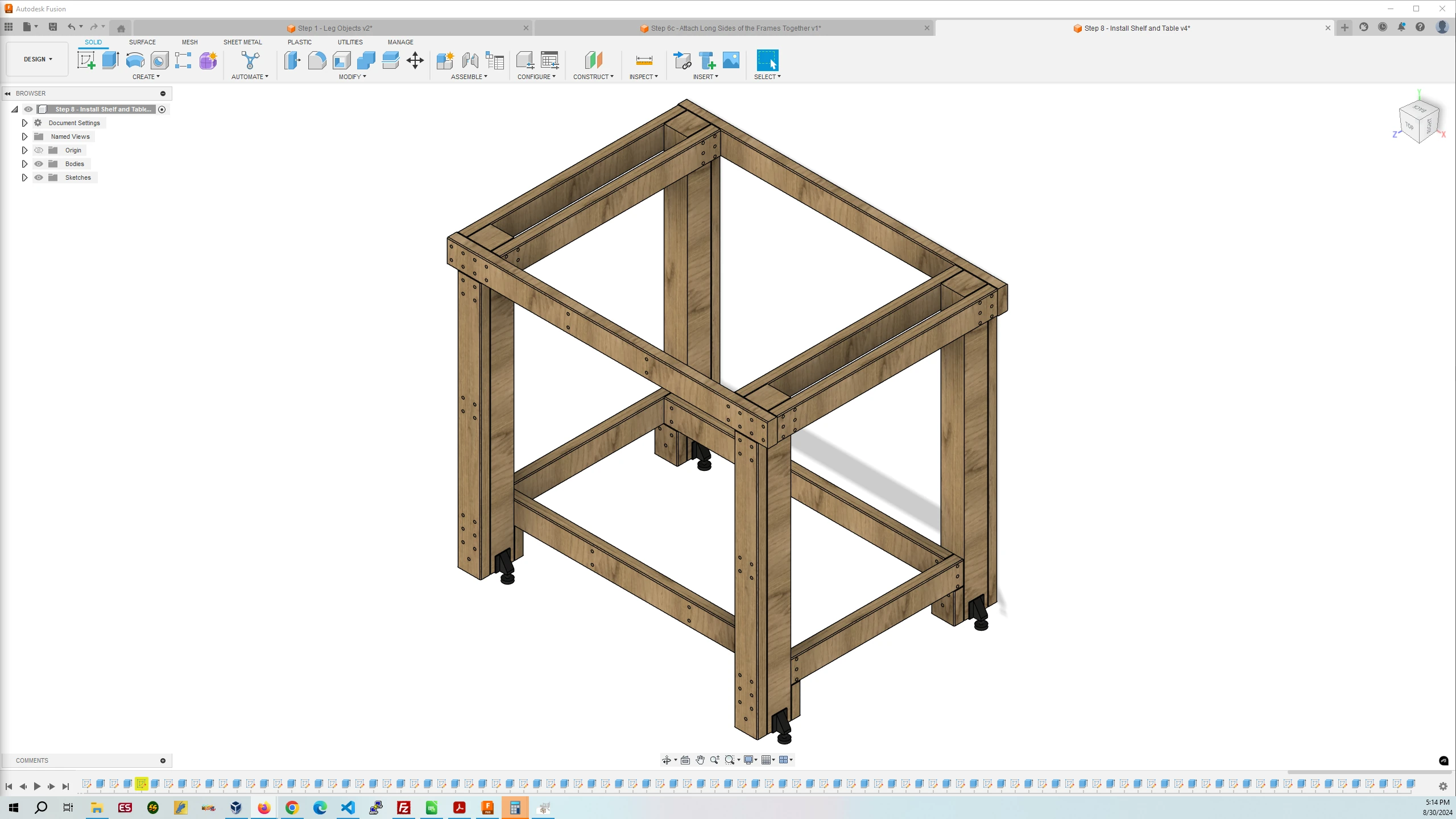
7d. Install Horizontal Supports and Computer Station Drawer Sides
This step is easy, merely clamp the horizontal table and shelf supports to the frames before you screw them together.
Position the drawer sides up against the Horizontal Leg Attached Table Supports and clamp them in place. Then proceed to screw the sides to the 4″x4″s. Then screw the drawer slides to the drawer sides.
After that is done proceed to attach the drawer slides to the drawer. Don’t install the drawer just yet, you will do that after the table top has been attached to the frame of the workbench.
You are now done assembling the frame of the workbench.
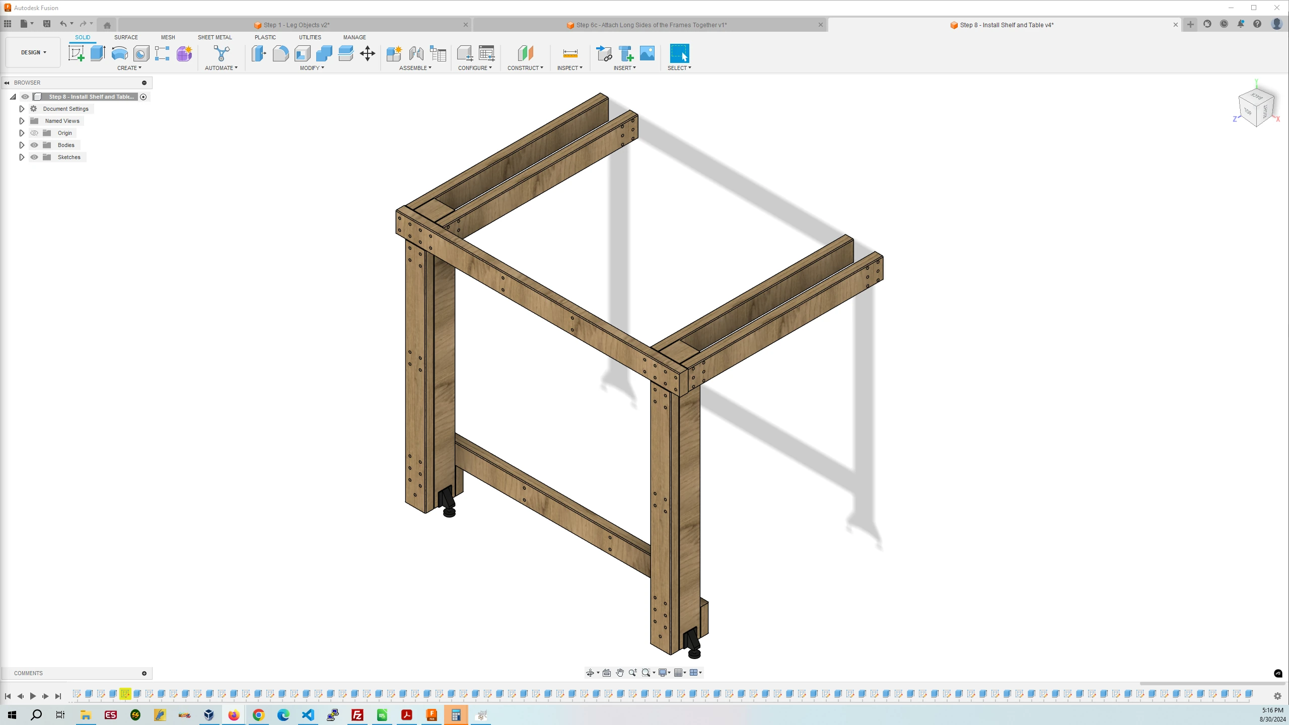
8. Install the Table Top
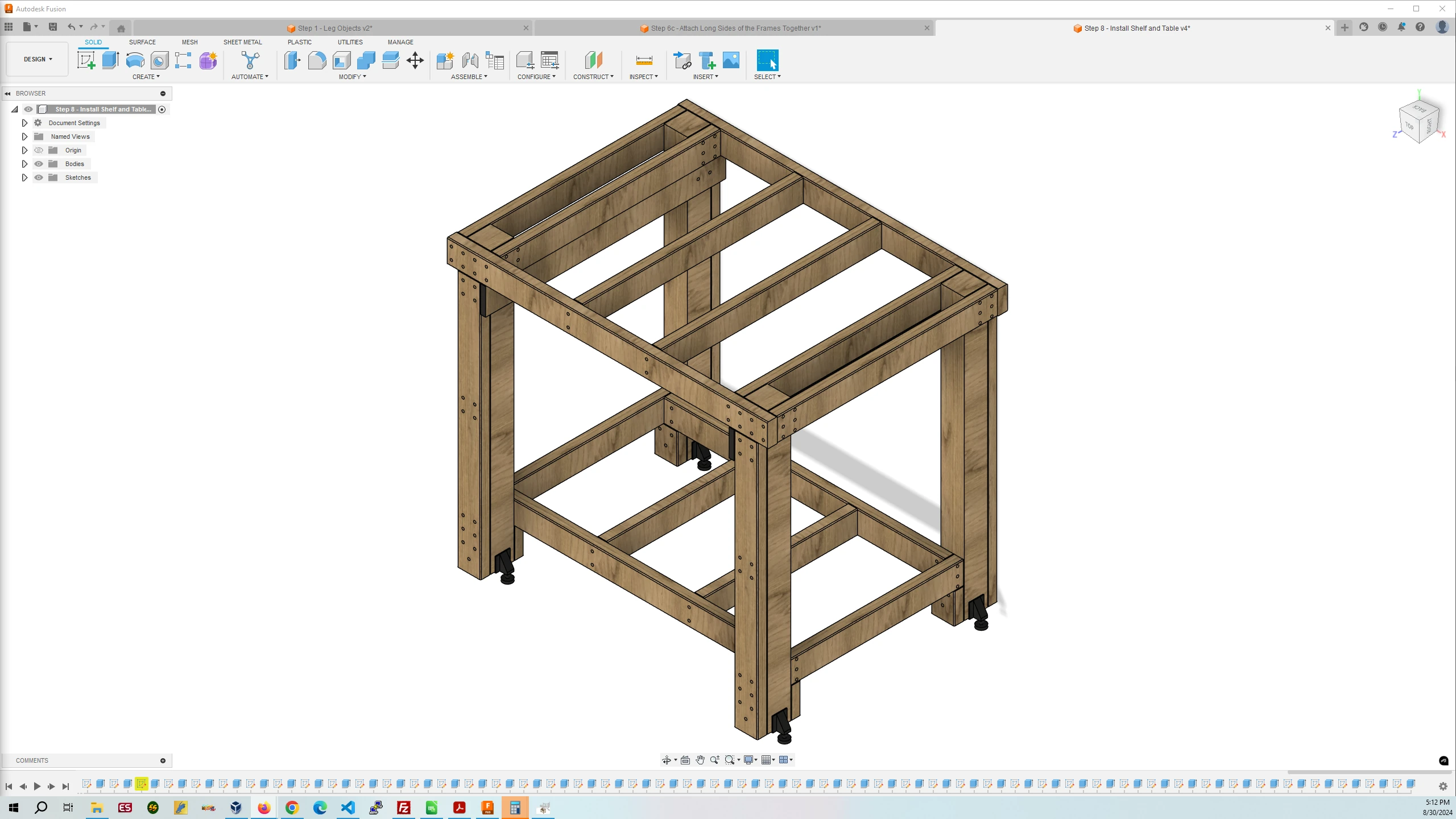
For installing the table top we will be using L brackets that will attach to the frame and to the underside of the table top. That way you will have a nice table top without any fasteners showing. The plywood is 3/4″ thick so we will be using 1/2″ screws. We will be attaching the L brackets to the inside Horizontal Leg Attached Table Supports, the Horizontal Table Supports, and the Long Table Supports. The mounting doesn’t have to be exact but try to space them out as shown in the image below.
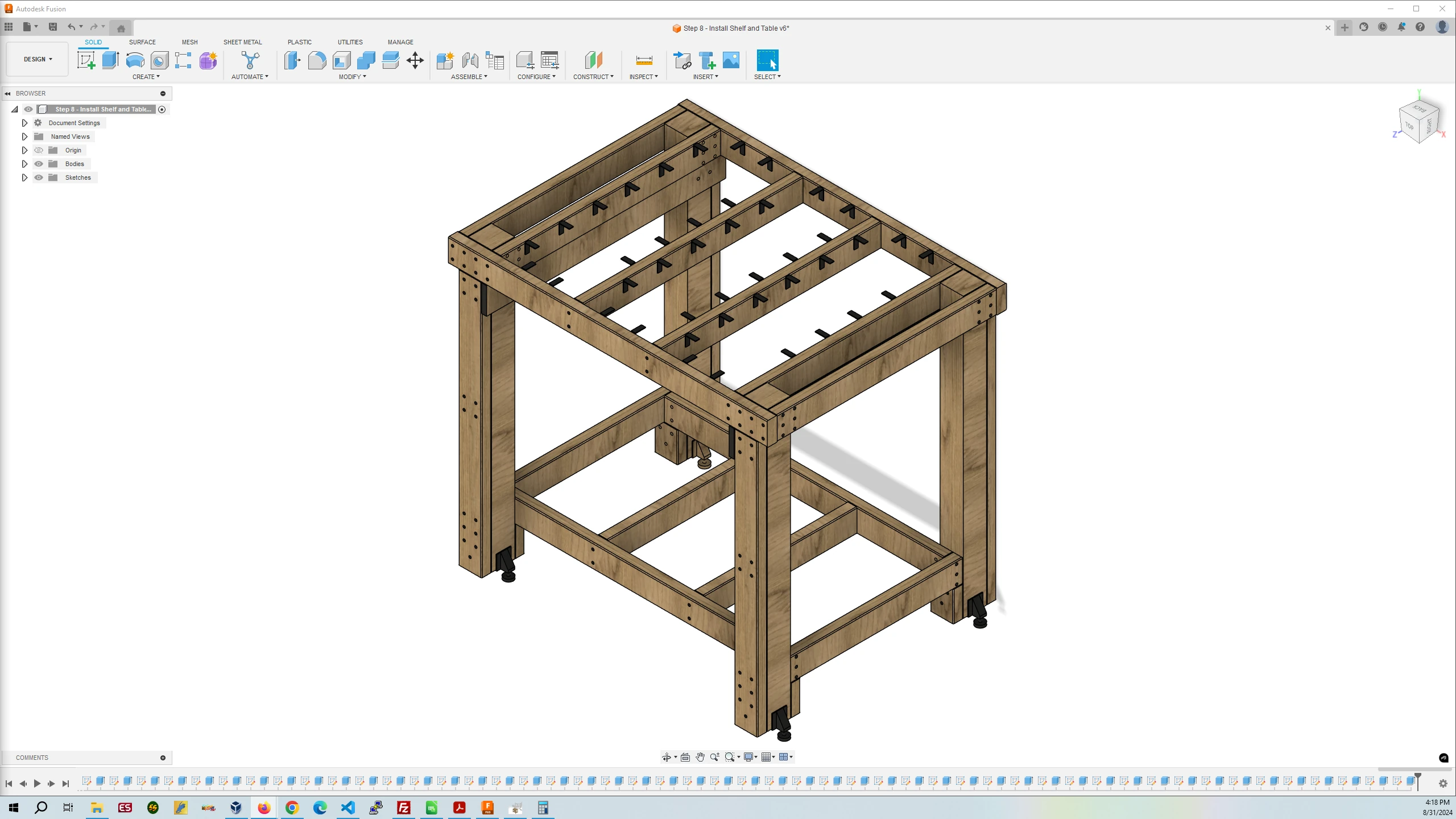
First, clamp the plywood on the left side of the frame on each side of the table in between the eight counterbored screw holes and the two counterbored holes to the right of them on the Long Table Supports. Then proceed to attach the L brackets to the plywood top. It is vital that you leave a space of about 3.5″ from the inside edge of the Long Table Supports as shown in the image below so the brackets won’t collide with the legs of the MPCNC that you will be building later. Do make sure to only use four L brackets on the right Horizontal Leg Attached Table Support and on the left side of the left Horizontal Table Support. This is to leave room for the four 1/4″-20 threaded inserts you will install in the table top to mount the spoilboard for the MPCNC router.
After the L brackets are attached to the plywood top then screw the brackets to the frame. Attaching the brackets in this order will prevent the L brackets from being attached to high on the frame pushing the table top up off of the frame.
Proceed to do this for the rest of the Horizontal Table Supports and the other inside Horizontal Leg Attached Table Support.
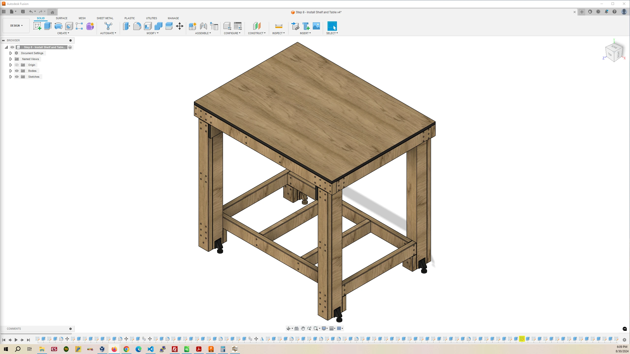
You are now done attaching the table top to the frame.
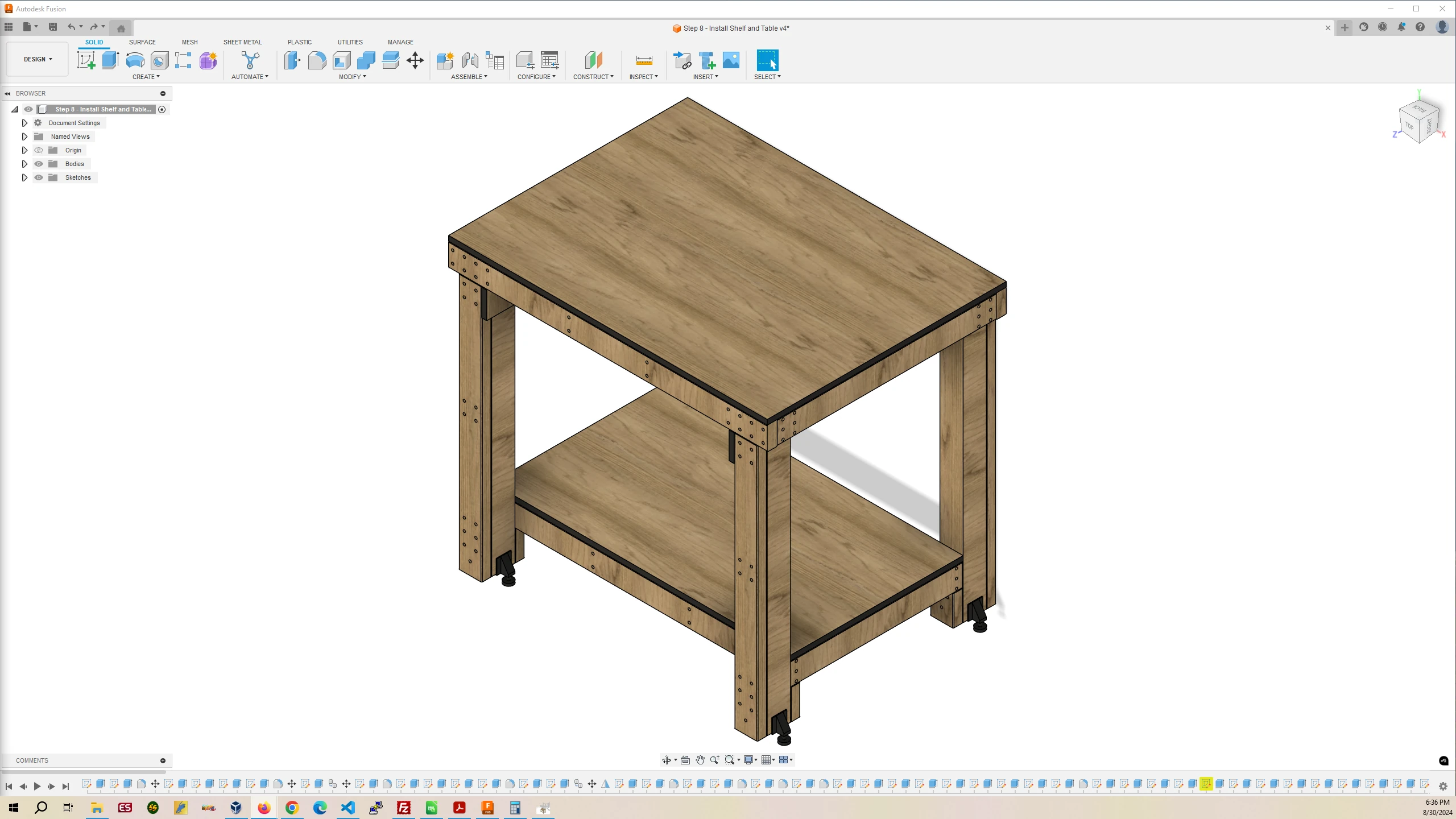
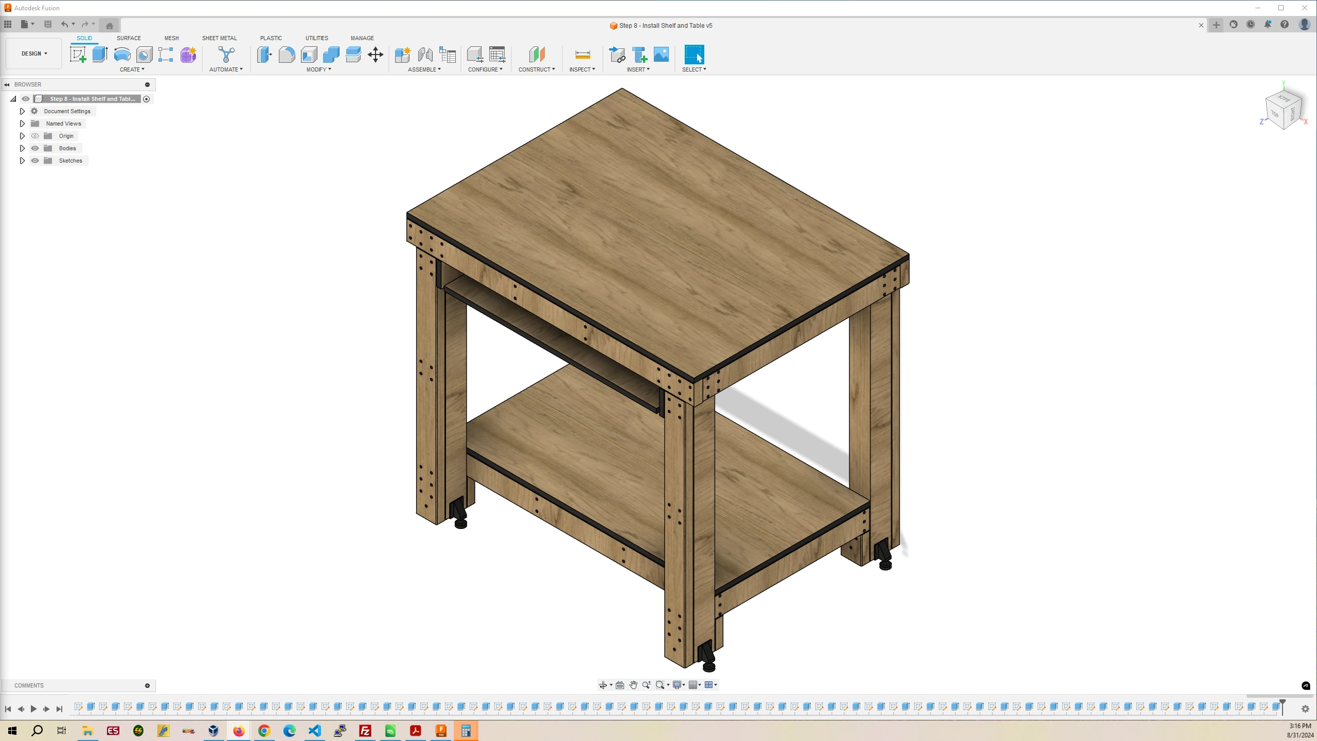
9. Install the Shelf, Computer Station Drawer and Plugs
Getting the plywood shelf into place is a little tricky as the fit is tight. Do your best to fit it in flatly. You can angle one long side a little bit and then use the piece of scrap on top of the shelf and hit the scrap with a hammer going back and forth until the shelf is flat on top of the frame. There is no need to use fasteners on the shelf.
After that, slide the drawer onto the drawer slides.
The plugs are optional, if you want, install the plugs into all the counterbored holes.
You are almost finished.
10. Install the Computer Work Station
If you don’t have an old flat screen monitor lying around that will fit in the drawer compartment along with a Raspberry Pi you aren’t using then I suggest buying an entry level, cheap as you can get including used, Chromebook to control the 3D printer and CNC router. I was lucky to have an old flat screen with a VESA mount which I bolted to the drawer along with a Raspberry Pi 4B that I wasn’t using. All the workstation will be doing is running the Chrome/Chromium web browser with a maximum of two tabs, one for the 3D printer, and one for the MPCNC router, so the computer does not need to be powerful.
Your workbench is complete.