02/15/2025 – APEC 2/15: ET Technosignatures, Discontinuum Physics & Torsion
3:00pm PT – Robert Francis, Jr. – Magnet Free-Fall Experimental Overview
To date there have been no papers published in any physics journals covering free-fall experiments with magnets. Over the past several months I have been conducting and refining free-fall experiments with magnets in several configurations and have collected significant evidence that inertial mass reduction takes place when an object is surrounded by a dipole magnetic field moving in the direction of their north to south pole.
Original Libreoffice PowerPoint Presentation
Inertial Mass Reduction when Dipole Magnets Move in the Direction of their North to South Pole
History of Public Magnet Free-Fall Experiments
The idea of conducting free-fall experiments with magnets appears to have began with Boyd Bushman, a senior scientist at Lockheed Martin. Bushman was discussed in the documentary “From Here to Andromeda”. Out of the few magnet drop experiments publicly available on the web and referenced below, only Tom Mahood definitely dropped magnets in the direction of their north to south pole.
Names and Dates of Magnet Free-Fall Experiments
- Boyd Bushman – 12/12/1995
- Tom Mahood – 11/18/1999 & 12/07/1999
- William Alek – 03/12/2009
- Magnet Tricks – 06/16/2015
- Rob Baker – 07/28/2017
- Elio Porcelli et al – 05/01/2021
- The Action Lab – 11/05/2021
- Robert Francis Jr – 09/14/2024 – Present
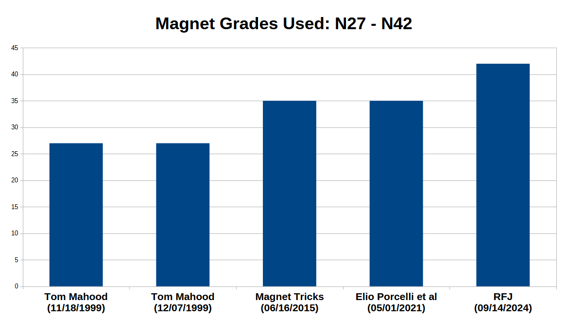
Magnet Grade
Others are Unknown
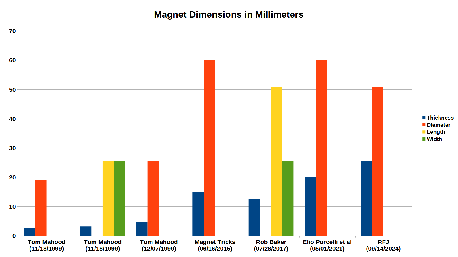
Magnet Dimensions
Others are Unknown
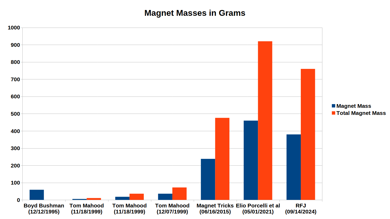
Magnet Masses
Others are Unknown
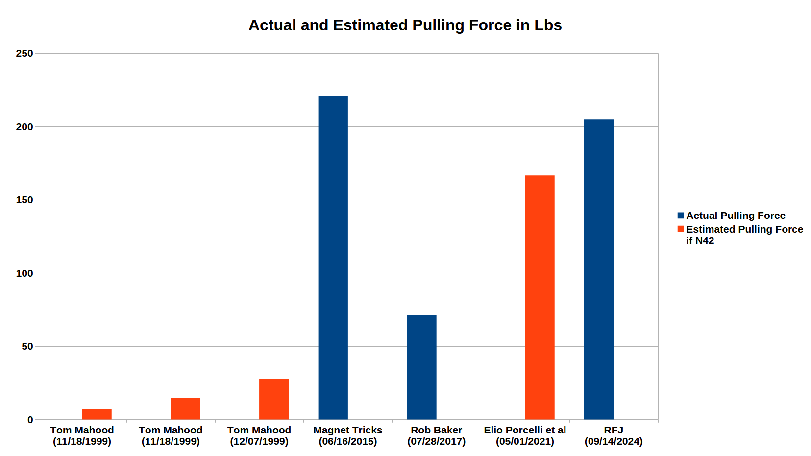
Magnet Pulling Force
Others are Unknown
Magnet Drop Height
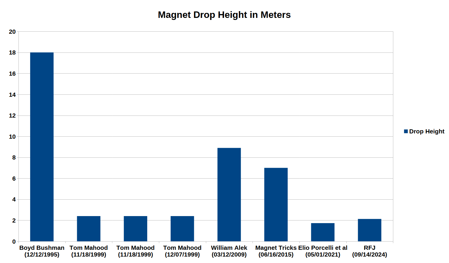
Others are Unknown
Experimenters Who Tested Dropping Magnets in the Direction of North to South Pole
- Tom Mahood (11/18/1999) – Recorded results of acceleration greater than Control but dismissed them as experimental error.
- Tom Mahood (12/07/1999) – Recorded results of acceleration lower than Control.
- Robert Francis Jr (09/14/2024 – Present) – Recorded results of acceleration greater than control.
Others Did Not Test or It is Unknown
Why Did I Record Results that Cannot Be Attributed to Experimental Error Unlike Mr. Mahood?
Mr. Mahood used magnets 19mm OD x 2.57mm (5.36 grams) and 25.4mm OD x 4.75mm (36.05 grams) with an estimated pulling force of 7.01 lbs and 27.8 lbs respectively. He also used an optical sensor that was unable to measure the g-forces experienced by the magnet objects during free-fall, just the time in between the start and stop of free-fall.
I used magnets 50.8mm OD x 25.4mm (380 grams) with an estimated pulling force of 205 lbs. I used an accelerometer that was able to measure the progressive acceleration of the magnet object during free-fall and able to see from the data that the magnet object continued to increase in acceleration until collision with the ground.
Did Boyd Bushman Lie?
As a senior scientist at Lockheed Martin, Bushman must have held a security clearance. During his time at Lockheed did he develop or become aware of inertial mass reduction technology? Did he learn an object with a dipole magnetic field moving in the direction of its north to south pole experienced inertial mass reduction?
Bushman claimed that the magnet drop experiments he conducted used a non-magnetic control and two repulsively coupled magnets bolted together. The objects looked the same on the outside. In Bushman’s experiment he hand dropped both objects at the same time with the personnel on the ground stating which object landed last. No measurement with an accelerometer or a timer to determine free-fall duration was used
Bushman easily could have used two magnets, attractively coupled, falling in the direction of its north to south pole with the other object being a control. Perhaps Bushman hoped that discussing his experiment publicly would lead to other scientists conducting more exhaustive experiments and the truth of inertial mass reduction technology would become public knowledge.
Mark 1 Free-Fall Object Experiment
Twenty Five Trials Conducted Per Each Free-Fall Object
Objects Hand Dropped
- Control (Non-Magnetic Steel Washers)
- Control AUD (Arduino Upside Down)
- NS/NS
- NS/NS AUD (Arduino Upside Down)
- NS/SN
- SN/NS
- SN/SN AUD (Arduino Upside Down)
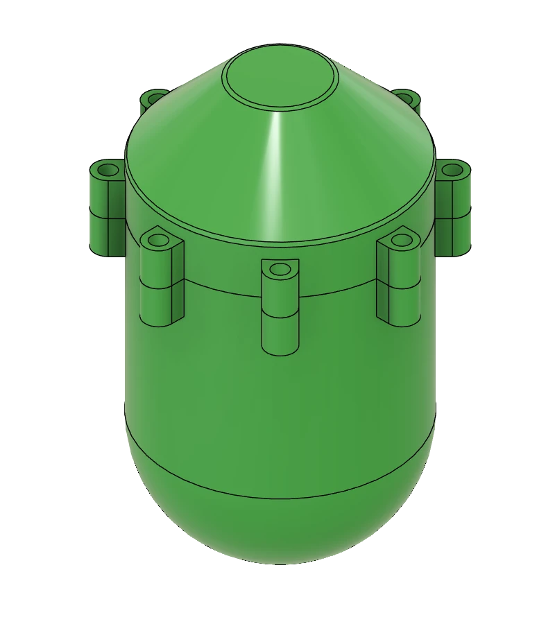
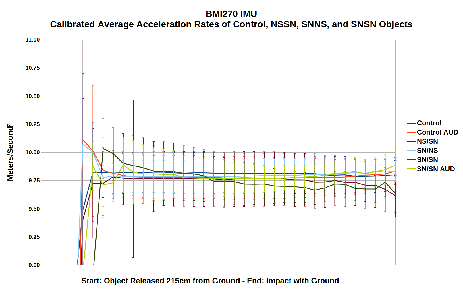
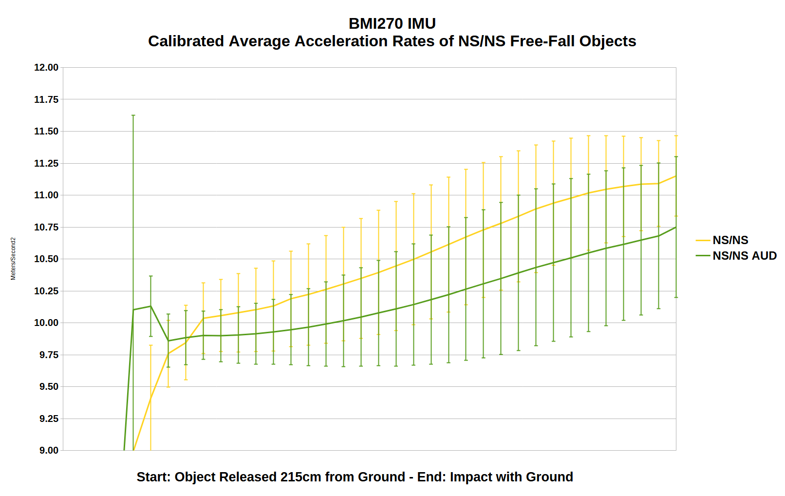
Only the NS/NS Magnet Free-Fall Object Exceeded 10.0m/s2
The NS/NS magnet object with two magnets attractively coupled moving in the direction of its north pole to south pole was the only one to experience continuous acceleration until hitting the ground at an average 11.125 meters/sec2.
Four Hypotheses
- The NS/NS magnet’s field increases its gravitational mass causing it to fall faster.
- The NS/NS magnet’s field decreases its inertial mass causing it to fall faster.
- The NS/NS magnet’s field both increases gravitational mass and decreases its inertial mass causing it to fall faster.
- The NS/NS magnet’s field contracts spacetime at its south pole and expands it at it’s north pole when in motion.
Mark 1 Gravitational Mass Experiment
Masses Virtually Identical
| Masses in Grams | ||||
|---|---|---|---|---|
| NSNS | NSSN | SNNS | SNSN | |
| Aluminum Bolt | 7.642 | 7.648 | 7.658 | 7.658 |
| Aluminum Washers (Qty 2) | 1.282 | 1.318 | 1.296 | 1.296 |
| Aluminum Hex Nut | 1.136 | 1.14 | 1.142 | 1.142 |
| Reported RY04X0 Magnet Mass (Qty 2) | 760 | 760 | 760 | 760 |
| Magnet Object Total Mass | 771.096 | 771.094 | 770.968 | 771.132 |
Gravitational Mass Modification Cannot Be Responsible
If the NS/NS free-fall object was modifying gravitational mass to increase its free-fall acceleration the object would be the heaviest magnet object weighed by the analytical balance. It was not, which eliminates hypotheses 1 and 3.
When you have eliminated the impossible, whatever remains, however improbable, must be the truth.
Inertial Mass Modification
or
Spacetime Contraction/Expansion
Must be Responsible
Mark 5 Free-Fall Object Experiment
Fifteen Trials Conducted Per Each Free-Fall Object Using NS/NS Magnet
Each Taper Type Tested with Five Different Fin Sizes
Objects Hand Dropped
- 45 Deg Back Taper
- 55 Deg Back Taper
- 65 Deg Back Taper
- 75 Deg Back Taper
- No Fins
- 5mm Height x 20mm Long Fins
- 5mm Height x 25mm Long Fins
- 10mm Height x 20mm Long Fins
- 10mm Height x 25mm Long Fins
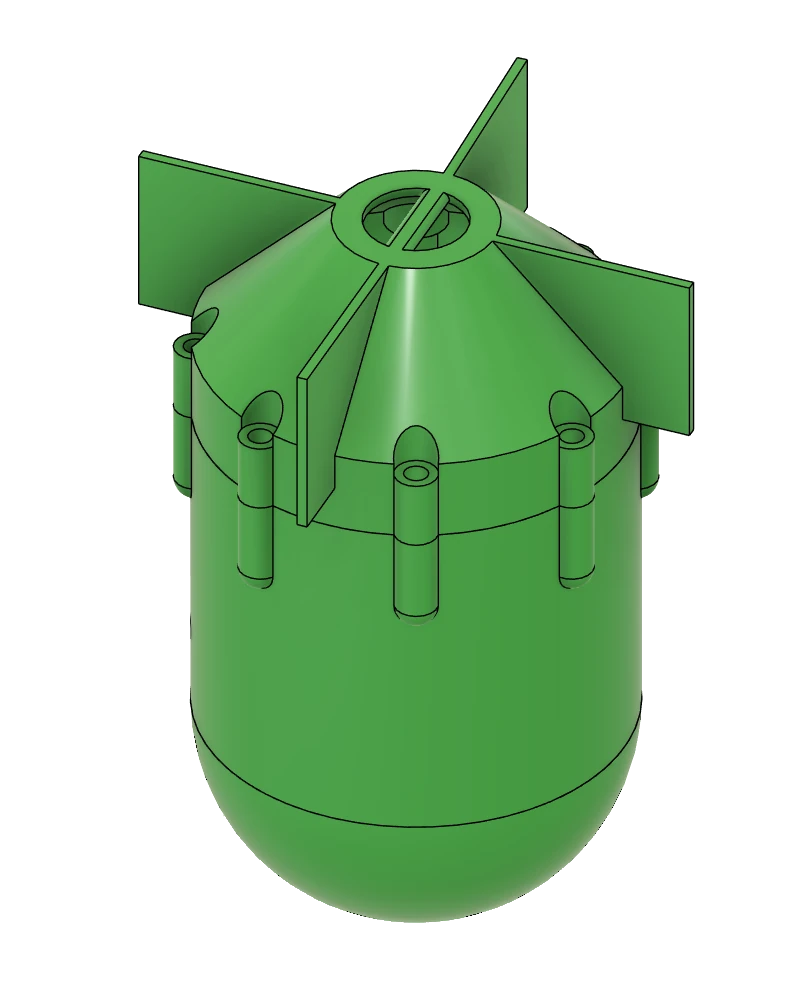
Successful Modifications
Minimizing Shell Size
- The complete Mark 1 plastic shell was reduced in length from 120mm to approximately 90mm in the Mark 5 models.
- The inner diameter of the shell was reduced from 64mm to 59.55mm.
Aerodynamic Improvements
- The attachment points in the bottom and top half of the shell were moved partially internal. The holes in bottom shell were tapped and the top shell was attached to those threads with M3 nylon machine screws.
A New Accelerometer
- The original Accelerometer in the Arduino Nano 33 BLE Rev2 board was not as accurate as I would have preferred. In it’s place I am now using an Adafruit BNO055 IMU connected to the I2C port of the Nano.
- The new IMU has auto-calibration and also converts the G-Forces to Meters/Second2 making generating the data easier as well.
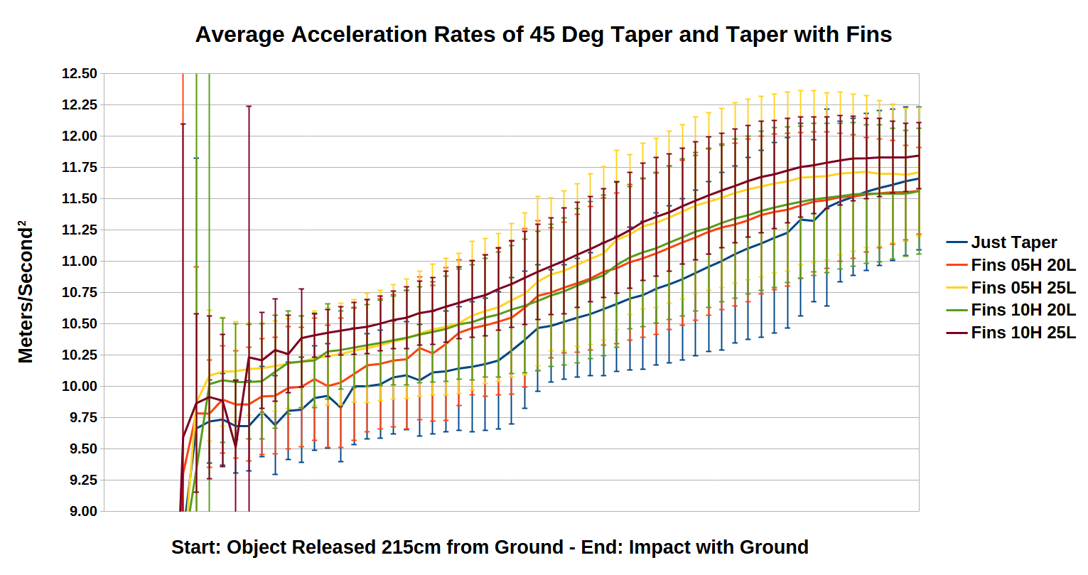
Average Acceleration Rates of 45 Degree Taper Variants
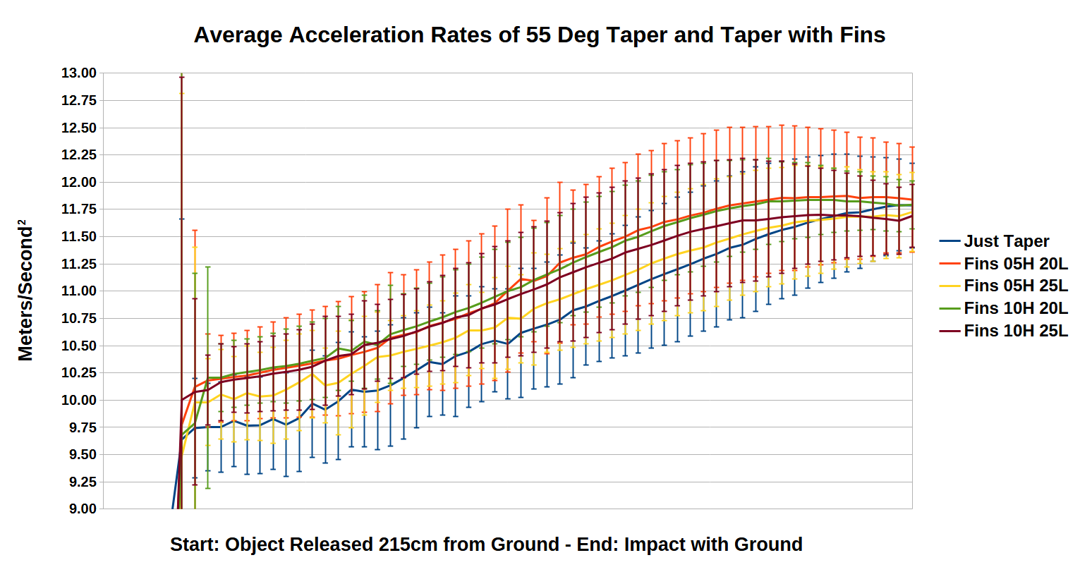
Average Acceleration Rates of 55 Degree Taper Variants
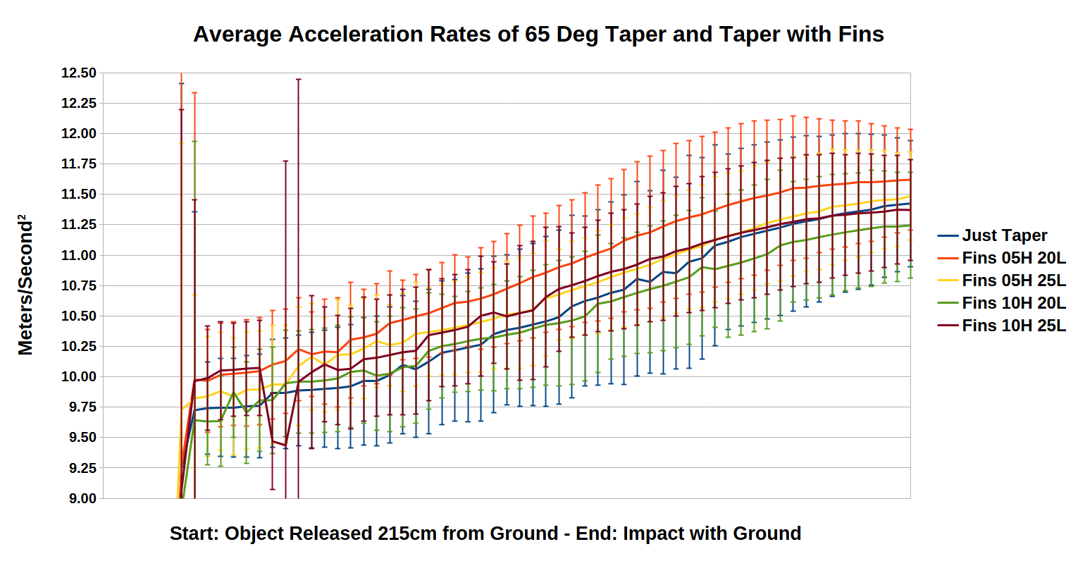
Average Acceleration Rates of 65 Degree Taper Variants
Average Acceleration Rates of 75 Degree Taper Variants
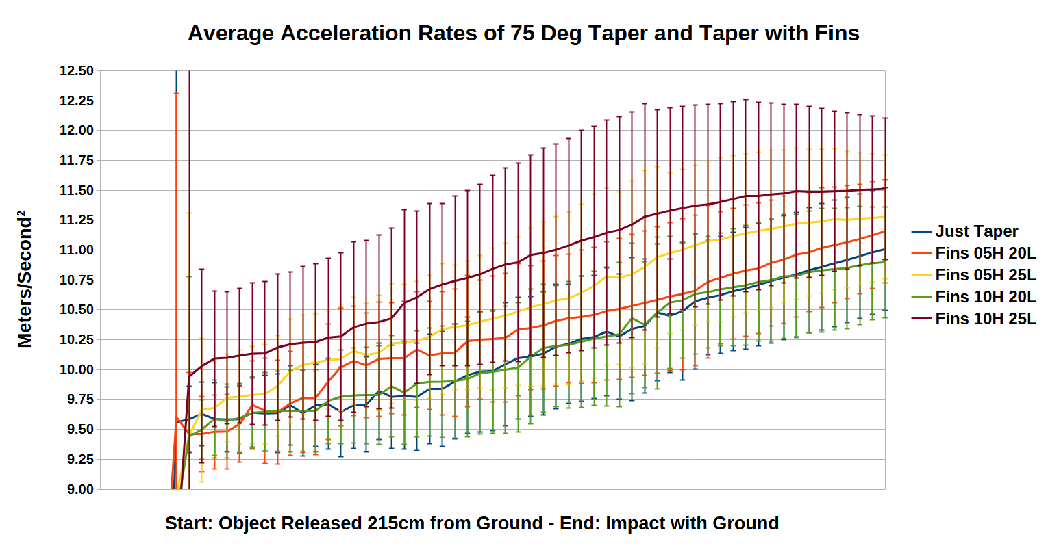
An Acceleration Gain of 0.75 Meters/Second2
Comparing data from the Mark 1 to the Mark 5 experiments which both drop the dipole magnet from a height of about 7 feet show a gain in acceleration from 11.1509 m/s2 to 11.8448 m/s2 due to the decreased shell size, decrease in foam used within the shell, and aerodynamic improvements.
Mark 5A & 8 Free-Fall Object Experiment
Twenty-Five Trials Conducted Per Each Free-Fall Object
The Mark 5A & 8 experiments are the first to use a computer controlled release mechanism instead of dropping the objects by hand.
A small piece of fishing line is inserted into a small hole at the back of the free-fall object shell with several overhand knots tied inside to prevent the fishing line from pulling back out of the hole.
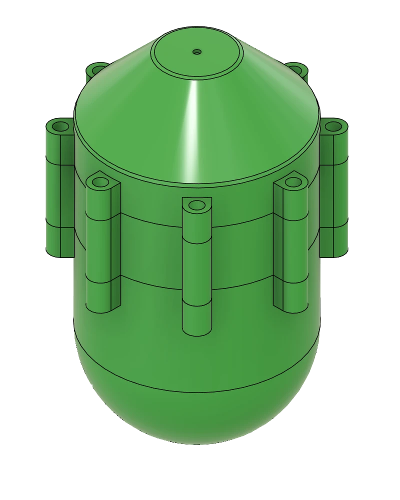
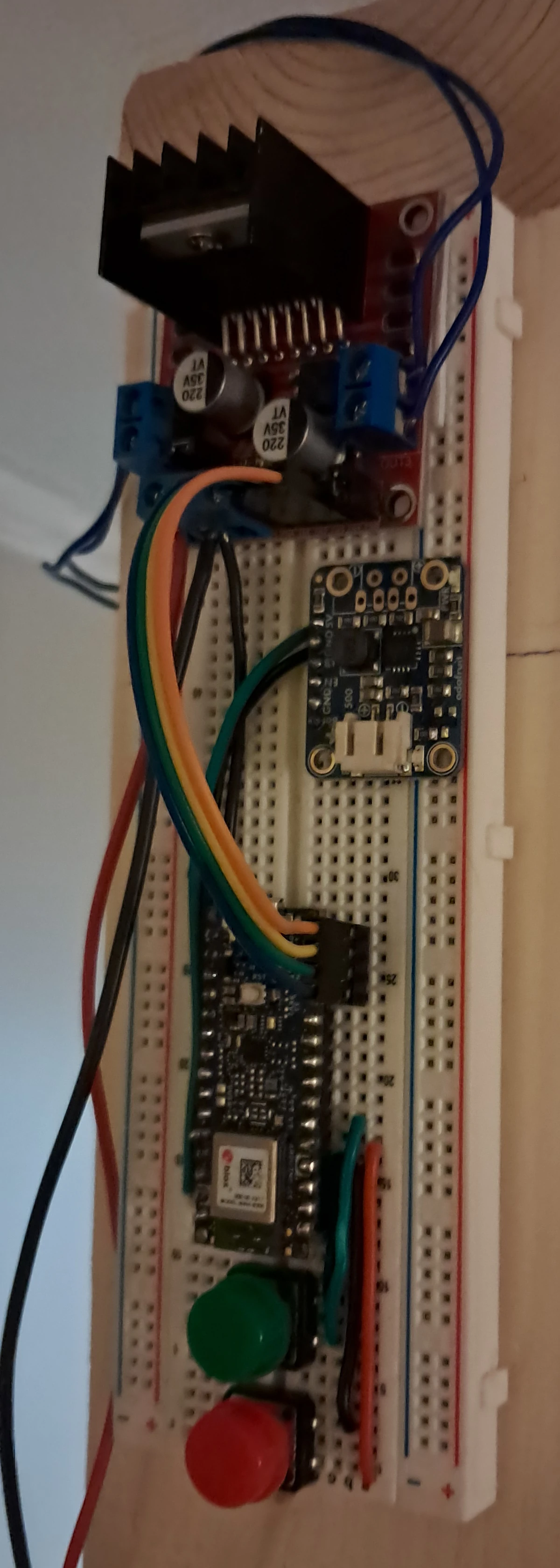
Mark 5A & 8 Experimental Method
- The fishing line with the attached free-fall object is inserted between the two attractively oriented solenoid coils controlled by an Arduino Nano.
- The red button on the breadboard is pressed to turn on the two solenoids and then I physically push them together where they then trap the piece of fishing line.
- Using Serial Bluetooth Terminal on my cellphone I send a command to the Arduino Nano inside the free-fall object to start recording accelerometer and gyroscopic data using the attached BNO055 IMU running in IMUPLUS – VECTOR_LINEARACCEL mode which runs for a few seconds.
- The green button on the breadboard is then pressed to deactivate the two solenoids dropping the object.
- I then use the Serial Bluetooth Terminal program to transfer the recorded data to my cellphone for future analysis.
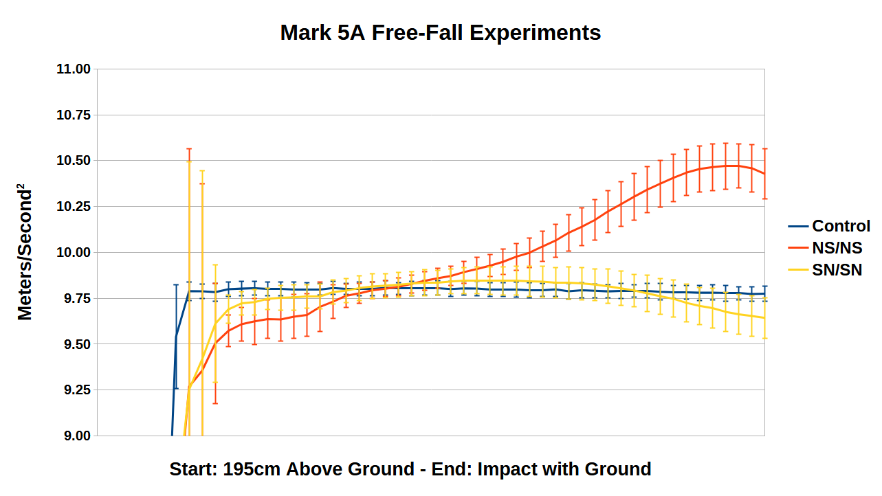
Mark 5A Free-Fall Object Experiment
Twenty Five Trials Conducted Per Each Free-Fall Object
Objects Dropped by Computer Control
Control
NS/NS
SN/SN
The Mark 5A experiments use a modified Mark 5 shell with a small hole in the back for the fishing line to attach.
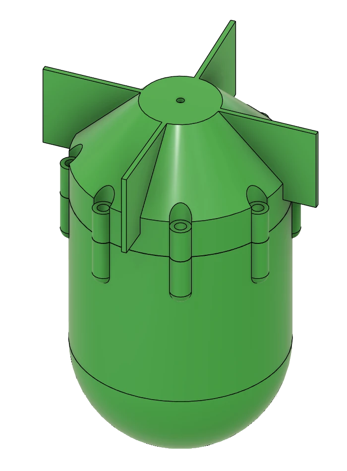
Mark 8 Free-Fall Object Experiment
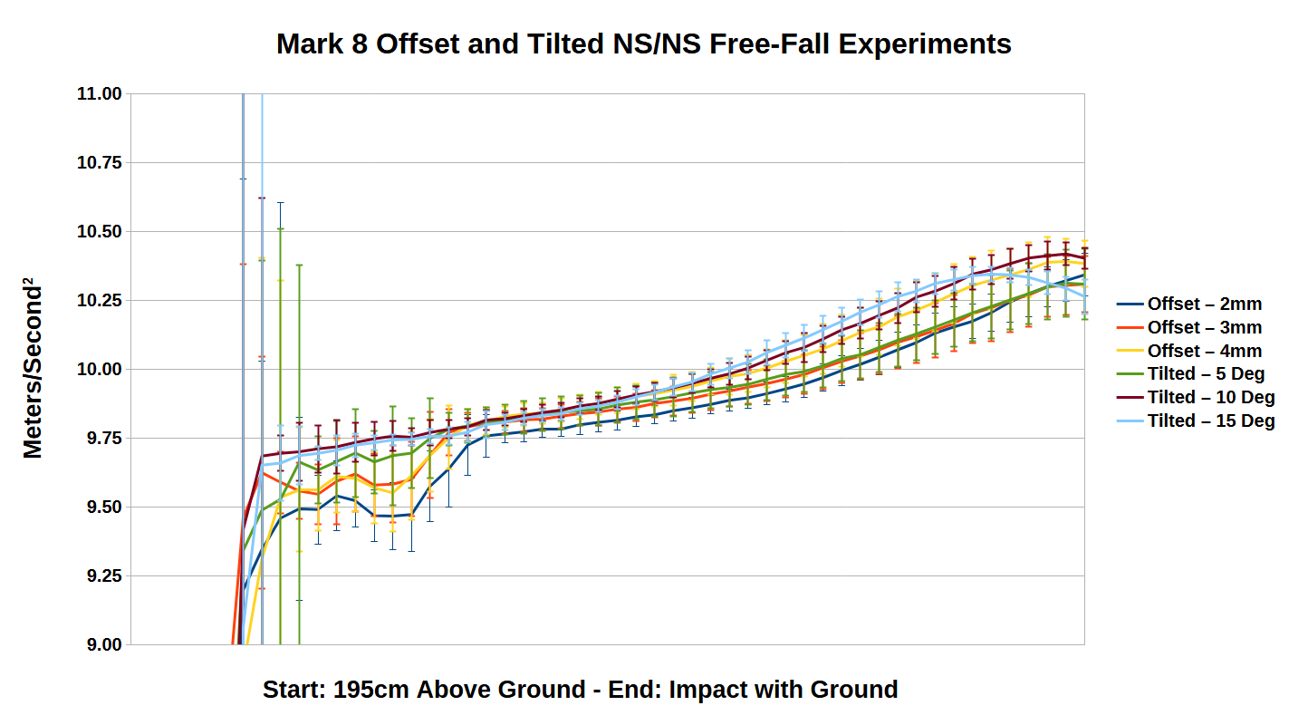
Twenty Five Trials Conducted Per Each Free-Fall Object
Objects Dropped by Computer Control
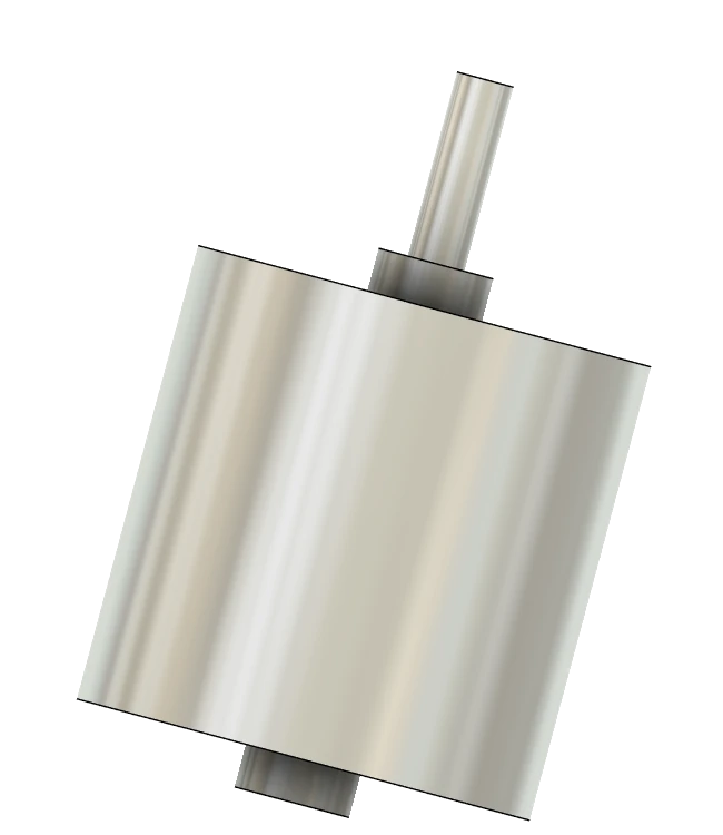
The Mark 8 experiments are also the first to include use of laterally offset as well as tilted orientations of the NS/NS magnet inside the free-fall object shell and foam.
These were tested in the hopes that with the center of mass not in the center of the free-fall object that it would induce a wobble and rotation of the free-fall object.
A static non-moving permanent magnet creates a static magnetic field but a static permanent magnet in motion creates a dynamic magnetic field with respect to it and other charged particles.
The “Alien Reproduction Vehicle”
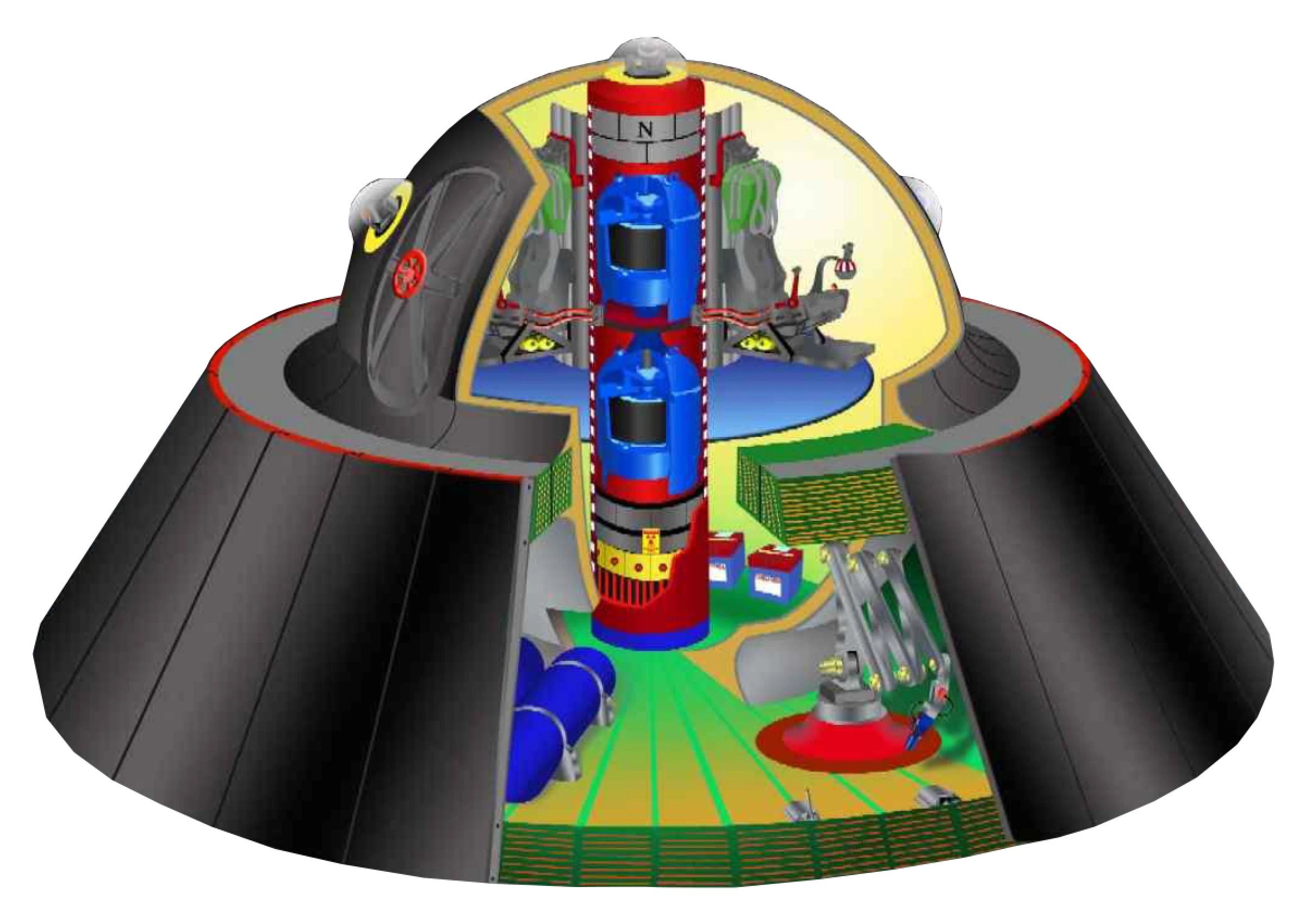
One highly controverstial UFO in the world of Ufology is the “Alien Reproduction Vehicle” as leaked by Brad Sorenson/Mark McCandlish and Leonardo Sanderson/Gordon Novel.
While its existence has never been proven it’s leak first occurred in 1988, a decade before Boyd Bushman conducted his magnet free-fall experiments.
The ARV was reported to have what looked like a solenoid coil around the circumference of the craft at its midpoint. Solenoid coils have a north and south pole just like the permanent magnets I used in my experiments.
It’s quite possible that UFOs use solenoid coils for inertial mass reduction of their craft, as well as shielding the craft from cosmic rays or the solar wind.
It is also possible that inertial mass reduction takes place to such an extent that the solenoid coil enables faster than light propulsion.
Hypothesis on the Cause of Inertial Mass
The Casimir effect was first predicted in 1948 to arise from quantum fluctuations, the generation of virtual particles, in the vacuum and was first experimentally proven in 1997.
The Casimir effect is an extremely short range effect only imparting a significant force at distances less than 1 micrometer. When two uncharged conductive plates are placed in a vacuum at distances apart of less than 1 micrometer the Casimir effect imparts less of a force pushing the plates outward then it does pushing the plates inward resulting in the conductive plates being pushed together.
I hypothesize that when an object is accelerating an asymmetrical Casimir effect is experienced by the object as one side of the object is receding from the force responsible for the Casimir effect and the other side is advancing on that force. I believe the Casimir effect is at least partly responsible for the phenomenon of inertia.
Hypothesis on the Cause of the Casimir Effect
As was just established, the Casimir effect arises from quantum fluctuations, the generation of virtual particles, in the vacuum. But what exactly is happening?
Virtual particles pop into existence as particle/antiparticle pairs, electron/positron pairs possibly in the bound state positronium, is such an example. They then annihilate creating short lived virtual gamma ray photons. I believe it is these, short lived, short range, virtual gamma ray photons that are the basis of the Casimir effect and responsible for the force behind the Casimir effect.
Controlling and Engineering the Casimir Effect
It is established that magnetic fields act on charged particles such as electrons and positrons but not on uncharged particles such as photons.
I hypothesize that the Casimir effect can be controlled with electromagnetic fields. Such fields need to act on the virtual electron/positron pairs while they are charged particles before they annihilate and become uncharged photons.
Electromagnetic fields can alter the axis of spin of electrons and positrons causing their axis of spin to align with the field lines of the magnetic field. When the virtual particle electron/positron pairs annihilate the vectors of the two virtual gamma ray photons will be aligned with the field lines of the magnetic field. If the field lines of the magnetic field mostly do not intersect with the accelerating object then the virtual gamma ray photons will mostly not collide with the object, imparting their energy.
I believe this to be the basis for the results seen with the NS/NS magnet objects.
Stronger magnetic fields have a greater ability to alter the axis of spin of electrons and positrons and align them with the magnetic field lines than weaker electromagnetic fields. Further, the greater an object’s acceleration, the stronger the magnetic field needs to be to alter the virtual particle pairs farther away from it.
I hypothesize that pulsed DC electromagnetic fields have a greater ability to engineer the Casimir effect than static fields. In my magnet free-fall experiments the fields are not entirely static even though I am using permanent magnets as the magnet is in motion and wobbling at the front and therefore applies somewhat of a dynamic field on any virtual electrons and positrons.
I hypothesize that high frequency pulsed electromagnetic fields have a greater ability to engineer the Casimir effect than low frequency pulsed fields as well as it increases the likelihood of altering the axis of spin of an electron/positron pair before it annihilates.
Free Energy
by
Controlling and Engineering the Casimir Effect
So far we have discussed engineering the Casimir effect in order to prevent the virtual gamma ray photons from colliding with an object using a magnetic field for the purposes of inertial mass reduction.
Now we will discuss engineering the Casimir effect to purposely cause one of the two virtual gamma ray photons from each annihilation to collide with a turbine blade whose apparatus is attached to an alternator to generate electricity.
Halbach Array
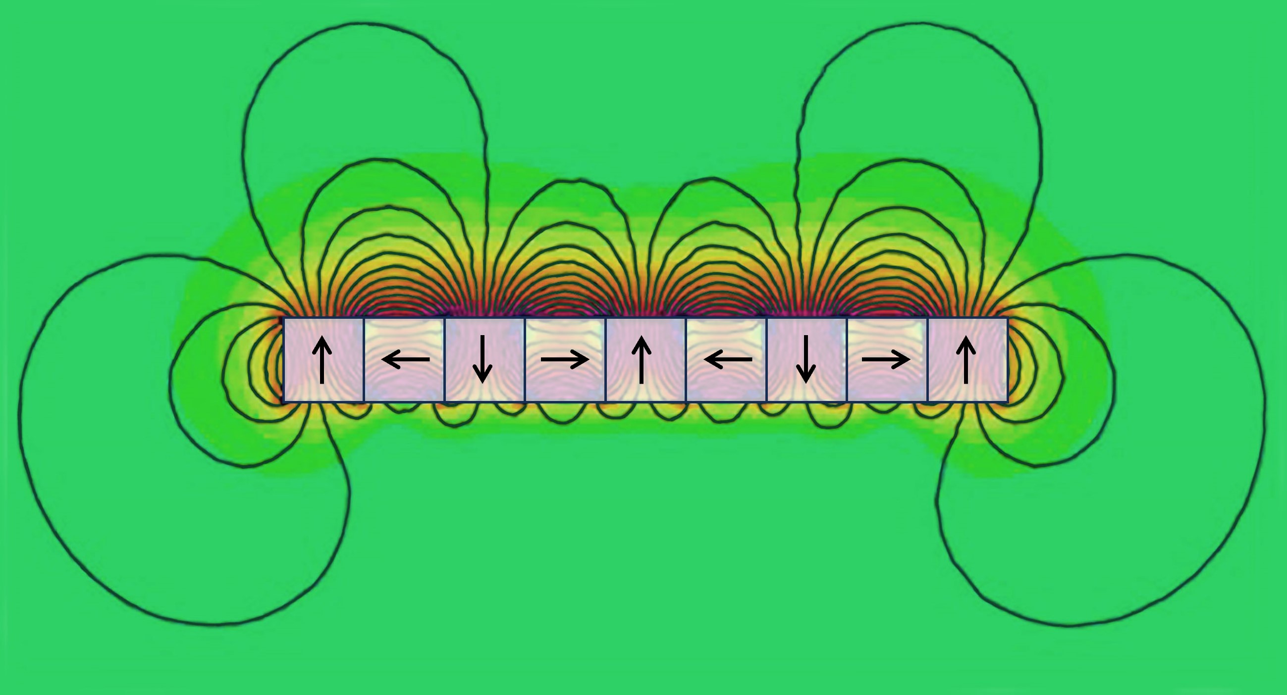
What is a Halbach Array
A Halbach array is an arrangement of permanent magnets that strengthen the magnetic field on one side of the array while canceling the field to near zero on the opposite side of the array.
If the permanent magnets are arranged with the field of the first magnet Left, then Down, then Right and finally Up in a repeating pattern, the field would be strong on the top and weak on the bottom as seen in the image on the previous slide.
If the permanent magnets are arranged with the field of the first magnet Left, then Up, then Right and finally Down in a repeating pattern, the field would be strong on the bottom and weak on the top.
A Halbach array is traditionally made with permanent magnets but for our purposes electromagnets are needed.
Why a Halbach Array?
With high frequency pulsed DC electromagnetic coils in place of the permanent magnets in the Halbach array, one side of the array will have a much greater ability to alter the axis of spin of the virtual electron/positron pairs than the other side that has virtually no field.
As a result on one side the virtual electron/positron pairs annihilate with their axis of spin perpendicular to the Halbach array with one virtual gamma ray photon flying away and disappearing back into the vacuum while the other will fly into the Halbach array imparting its energy and momentum.
On the other side of the Halbach array the virtual electron/positron pairs axes of spin will all be random due to the marginal magnetic field resulting in the virtual photons flying in all directions equally.
One side will have a traditional random Casimir effect force imparting energy to it while the other will have a much more polarized Casimir effect force imparting a greater amount of energy and momentum into it. This imbalance of force will result in rotation if built into a turbine.
Back to Free-Fall Experiments, Where to Go From Here?
Taller Fully Automated Drop Device Mark 2
In the time after I completed this presentation and before giving it tonight I have upgraded the drop device.
Now, when the green button is pressed a series of actions take place. The Master Arduino Nano ESP32 communicates with the Nano 33 BLE Rev2 in the free-fall object, first telling the IMU in the free-fall object to start recording. A timer starts in the Master Arduino and it releases the free-fall object.
When the object passes through an IR beam at the bottom of the drop device the IMU will stop recording and the timer will stop. The data is then sent over Bluetooth and saved as a .csv (spreadsheet) file on a microSD card connected to the Master Arduino for later analysis.
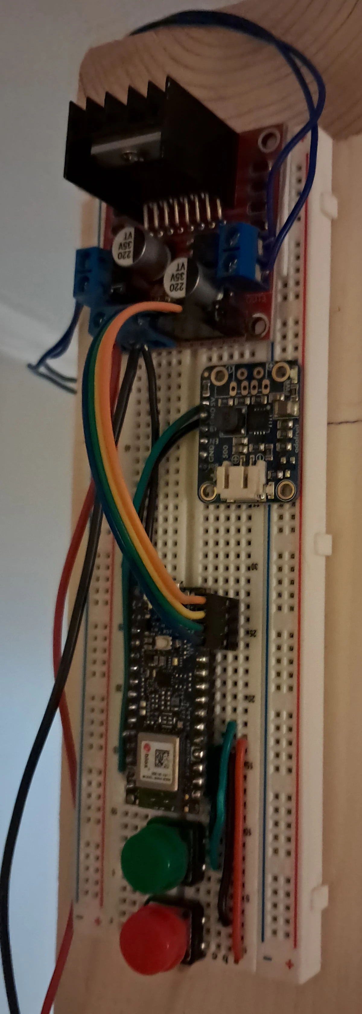
I intend to add camera recording functionality to videotape the free-falls. I will need to write some Arduino code for the Master Arduino Nano ESP32 to communicate via Bluetooth with my smartphone to initiate recording when the green button is pressed and deactivate it when the bottom IR beam is broken.
The next stage for the drop mechanism is to increase its height for use outdoors. The drop device will be fully automated. A single button press will start the series of trials.
A stepper motor attached to the free-fall object with fishing line will wind the free-fall object back to the top shutting off when the free-fall object blocks the top IR beam.
The two solenoid coils then activate holding the fishing line and free-fall object. The stepper motor will then unwind the fishing line. The object is then released breaking the bottom IR beam and the process repeats for the number of trials desired.
They say a picture is worth a thousand words. How many words is a video worth?
After giving it some thought I decided the taller fully automated drop device will be a dual drop device.
A physics paper with line charts and tables is all well and good but for the average person, and perhaps even those running physics journals, that is not enough. When extraordinary claims are being made many will want extraordinary evidence. I believe video evidence is more likely to convince skeptics than just about any other evidence.
The dual drop device will have the NS/NS free-fall object on one side and a Control object made of non-magnetic stainless steel 316 fender washers on the other. With the camera recording and with a higher drop distance and computer controlled simultaneous release I am hoping for clear video evidence that the NS/NS object reaches the ground sooner than the Control.
Replacing Permanent Magnets with an Electromagnetic Coil
I believe I am reaching the end in terms of dropping permanent magnets in the direction of their north to south pole. The field they put out is too static and they tend to rotate and fall sideways. Once the dual drop experiments are conducted I believe the next stage is building a pulsed DC electromagnetic solenoid style coil.
Such coils have a north and south pole and the field they put out will be far more dynamic than that of a moving permanent magnet.
I am envisioning a miniature basketball sized device about 6-8 inches in diameter.
- Dewalt Flexvolt power tool battery capable of 60 volts and very high amperage
- Gyroscope/Reaction Control Wheel at center mass
- Electromagnetic coil starting near the front extending back to around the mid circumference of the object
