10/12/2024 – APEC Open MIC
Updates on my magnet free-fall experiments – Recording their acceleration rates as they travel in the direction of north pole to south pole.
Original Libreoffice PowerPoint Presentation
Mark 1 – Original Magnet Free-Fall Experiment
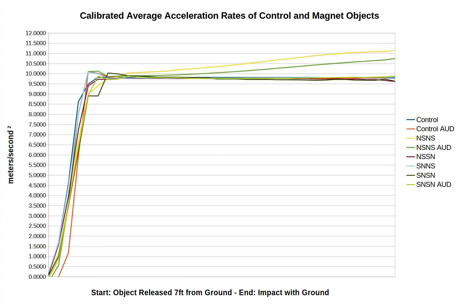
Mark 2 – Magnet Free-Fall Experiment
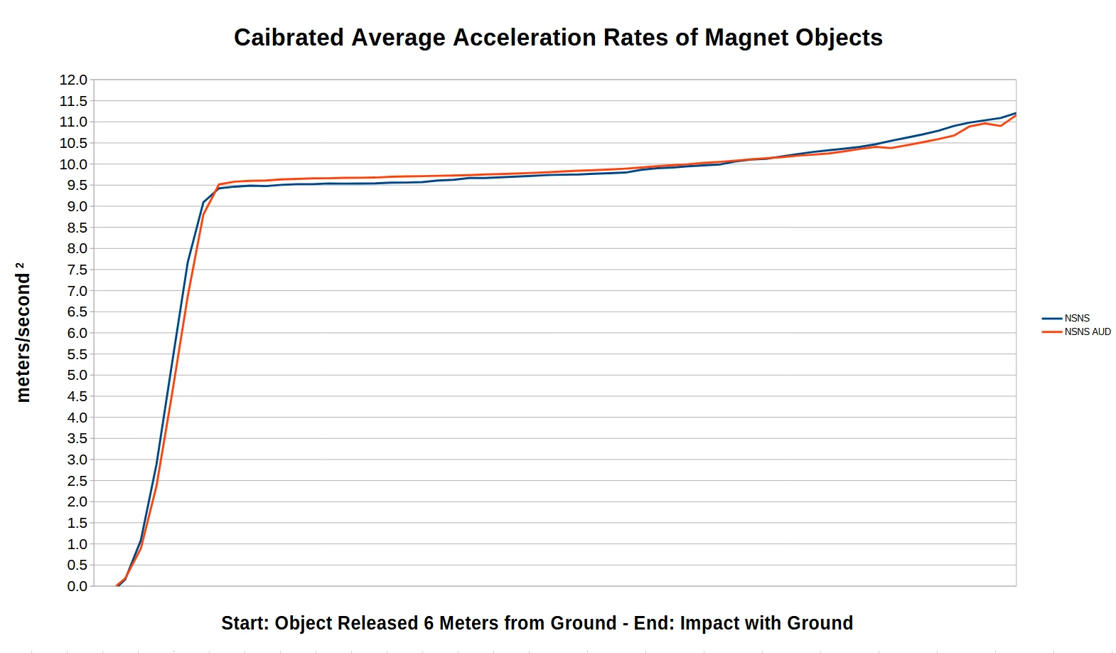
Why So Little Additional Acceleration From Four Additional Meters of Free-Fall?
Possibilities
- The acceleration of that magnet object is plateauing due to the size and strength of it’s magnetic field.
- The wind was affecting the magnet drops.
My Observations and Hypothesis
- From visual observation of the magnet objects during free-fall the object is unstable and rotates at around the two meter mark and from then on falls sideways rather than in the direction of north to south pole.
- The free fall environment is not as controlled as in my house. Wind is also an issue and needs to be better controlled.
Magnets Used and Their Magnetic Fields
Mark 1
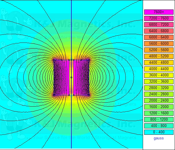
- K&J Magnetics
- Two Attractively Coupled RY04X0 Magnets
- Grade: N42
- Pull Force: 300.2 lbs
- Combined Dimensions:
- 2″ Diameter
- 2″ Thick
- Drop Distance: ~2 Meters
Mark 2

- K&J Magnetics
- Two Attractively Coupled RY04X0 Magnets
- Grade: N42
- Pull Force: 300.2 lbs
- Combined Dimensions:
- 2″ Diameter
- 2″ Thick
- Drop Distance: ~6.5 Meters
Mark 3
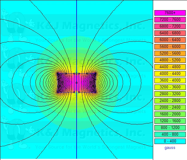
- K&J Magnetics
- One RY04X0 Magnet
- Grade: N42
- Pull Force: 205.3 lbs
- Dimensions:
- 2″ Diameter
- 1″ Thick
- Drop Distance: ~6.5 Meters
Mark 4
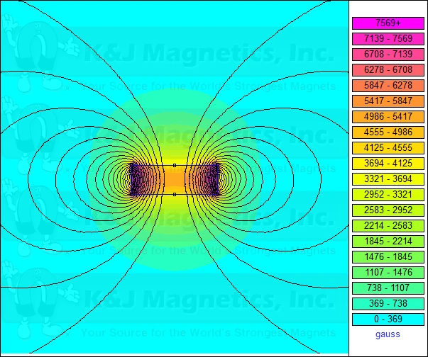
- K&J Magnetics
- One DZ0X0 Magnet
- Grade: N42
- Pull Force: 400.0 lbs
- Dimensions:
- 3″ Diameter
- 1″ Thick
- Drop Distance: ~6.5 Meters
Problems Encountered
It appears the Arduino Nano 33 BLE Rev2’s IMU is delivering some bad results.
- This is most apparent in the Mark 2 experiment with the differences between NSNS and NSNS AUD as well as SNSN and SNSN AUD.
- Turning the Arduino Upside Down should not change the accelerometer readings and yet there is over a 0.25meters/second2 difference between non-AUD and AUD experiment trials.
- Looking at the Acceleration Rate results in Mark 2 & 3 it also appears minus signs (-) are being added randomly to some results so instead of smooth acceleration curves the acceleration jumps between substantially less and substantially more than 9.8meters/second2.
- The IMU is only returning results every 20ms rather than the 10ms it is reported to be capable of. I don’t know if that is a result of waiting for the accelerometer and gyroscope to report being ready.
Other Problems
- The Mark 2 experiments were plagued with the magnet free-fall object rotating shortly after release and falling most of the way to the ground sideways.
- The Mark 3 experiments were using one magnet instead of two which decreased its inertial mass reduction potential, though it did tend to fall without rotating sideways.
- The Mark 3 and 4 experiments did not have an aerodynamic shell which could result in the objects suffering from greater wind resistance though the magnets used had a diameter greater than thickness which helped keep them falling in the direction north to south pole preventing rotation.
Hypothesized Solutions
Arduino Nano 33 BLE Rev2 IMU Improvements
- Conduct tests with the IMU near and far away from the NSNS magnet object to see if the magnet’s extremely high field is affecting the IMU’s accelerometer and gyroscope readings.
- If that is the case, add shielding inside the free-fall object’s shell, perhaps in between the layers of XPS foam and test again to see if the IMU behaves normally or erratically.
- If the magnet is not affecting the IMU I will buy another Arduino and PowerBoost board and hopefully that will solve the problem.
Aerodynamic Improvements to Ensure Free-Fall from North to South Pole
- Create a more aerodynamic shell. ChatGPT recommended a shell that is 2.5x – 3x as long as the object’s diameter to maximize aerodynamics.
- ChatGPT said to remove the external M4 Nylon screw attachment points and make them internal in the front half of the shell. I will use a tap to make the threads. In the back half I will use gullies on the outside of the shell to attach the screws into the front half of the shell.
- ChatGPT said to add more sleek fins to the shell at the very back such as a clipped, tapered, and swept fin design I ran across on a model rocket site.
Vertical Guide Wires
- If I am unable to create a free-fall object that falls vertically without rotation I will build a simple vertical wooden frame to run two guide wires from top to bottom.
- Guide wires will prevent the free-fall objects from being able to rotate and fall sideways although the more the free-fall object tries to rotate the more friction that will be created between the guide wires and the free-fall object shell.
- I intend to use PTFE coated fishing line for the guide wires and small PTFE tubing sections to slide along that fishing line.
- I have a couple different ideas for the frame in an effort to make it as easy, light, and cheap as possible.
Wind Blocking Device
- The 6-7 meter drops are conducted outside so I need to come up with a solution for eliminating the wind acting on the experiment.
- I was thinking of using very thin wire or rod and wrapping flooring paper around the vertical chamber I create with them. This will eliminate horizontal wind from affecting the experiment.
Further Research Necessary
Until I have the IMU working properly and solved the movement of the free-fall objects so they are always moving north to south pole it will remain unknow if the magnet objects plateau in their acceleration or if they continue to increase for as long as they travel.
