Build Magnet Free-Fall Object
The magnet free-fall object consists of the 3D printed plastic shell, the XPS foam encasement layers, the Arduino Nano 33 BLE Rev2, PowerBoost 500 Basic, a 3.7V Lipo 250mAh Battery, and the control and magnet objects.
Important note, the .gocde files for the milled parts are specifically made for my build of the MPCNC router. I recommend importing the .f3z files into Autodesk Fusion 360 and customizing them for your specific router setup.
An MPCNC build guide is in progress to enable you to build an MPCNC with the same configuration as my own and use the .gcode files.
- Let’s Look at the Material Requirements
- Print the Free-Fall Object Shell
- Surface and Cut the XPS Foam
- Mill XPS Foam Plates 1 through 6
- Install the Arduino IDE and Required Libraries
- Test the Arduino Nano’s IMU Accelerometer
- Solder the Arduino Nano to the PowerBoost 500
1. Let’s Look at the Material Requirements
2. Print the Free-Fall Object Shell
Download Free-Fall Object Bottom Shell
Download Free-Fall Object Top Shell
The plastic shell has a bullet shaped nose and four fins to try and keep the object moving vertically without tumbling. The shell itself is 1.5mm thick. There are eight holes on the top and bottom of the shell for fastening them together with M4 x 25mm Nylon screws and hex nuts. There is a half ring on the back of the top shell to tie a string or fishing line material to it to retrieve the object if dropped from large heights.
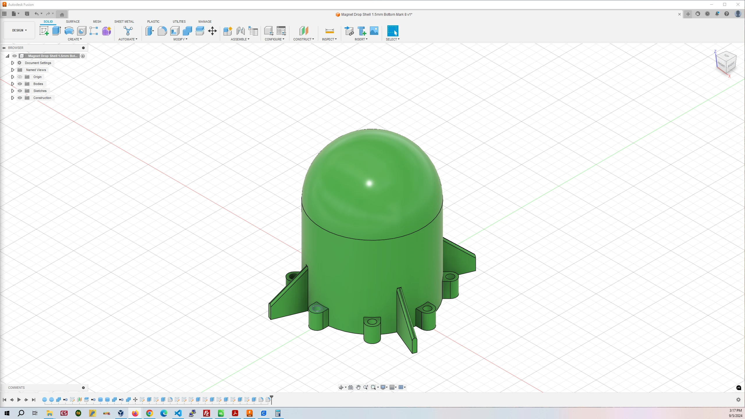
Free Fall Object Bottom Shell
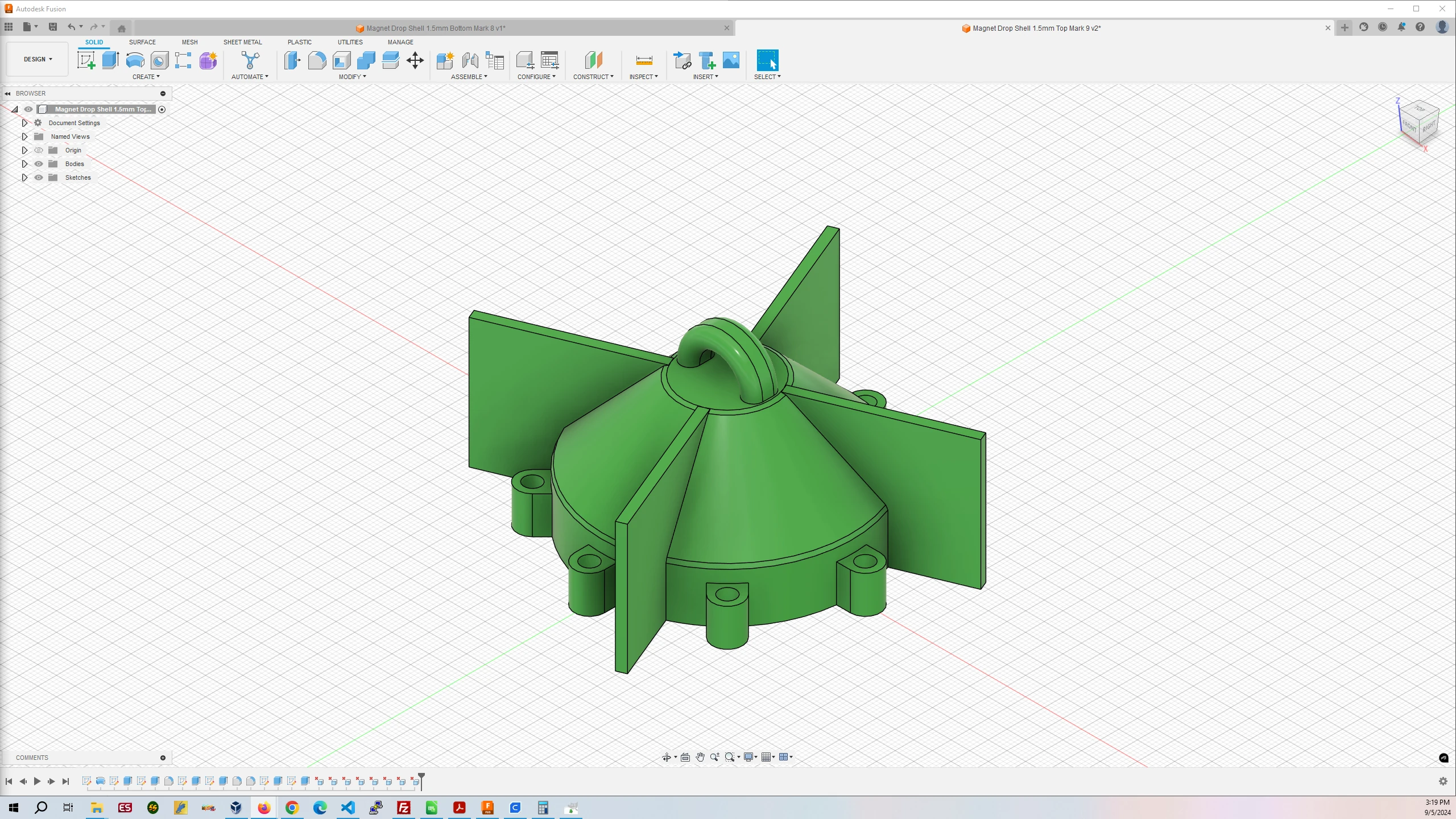
Free Fall Object Top Shell
Free-Fall Object Bottom Shell
Filament Used: 49g – 16.36m
Time to Print: 3 hours 28 minutes
- Ultimaker Cura Settings
-
- Walls > Wall Thickness > 2.0 mm
- Infill > Infill Density > 50.0%
- Support > Generate Support > Checked
- Support > Support Structure > Tree
- Support > Support Placement > Everywhere
Free-Fall Object Top Shell
Filament Used: 37g – 12.43m
Time to Print: 3 hours 0 minutes
- Ultimaker Cura Settings
-
- Walls > Wall Thickness > 2.0 mm
- Infill > Infill Density > 50.0%
- Support > Generate Support > Checked
- Support > Support Structure > Tree
- Support > Support Placement > Everywhere
3. Surface and Cut the XPS Foam
Download XPS Foam Surfacing Files
Download XPS Foam Cutting Files
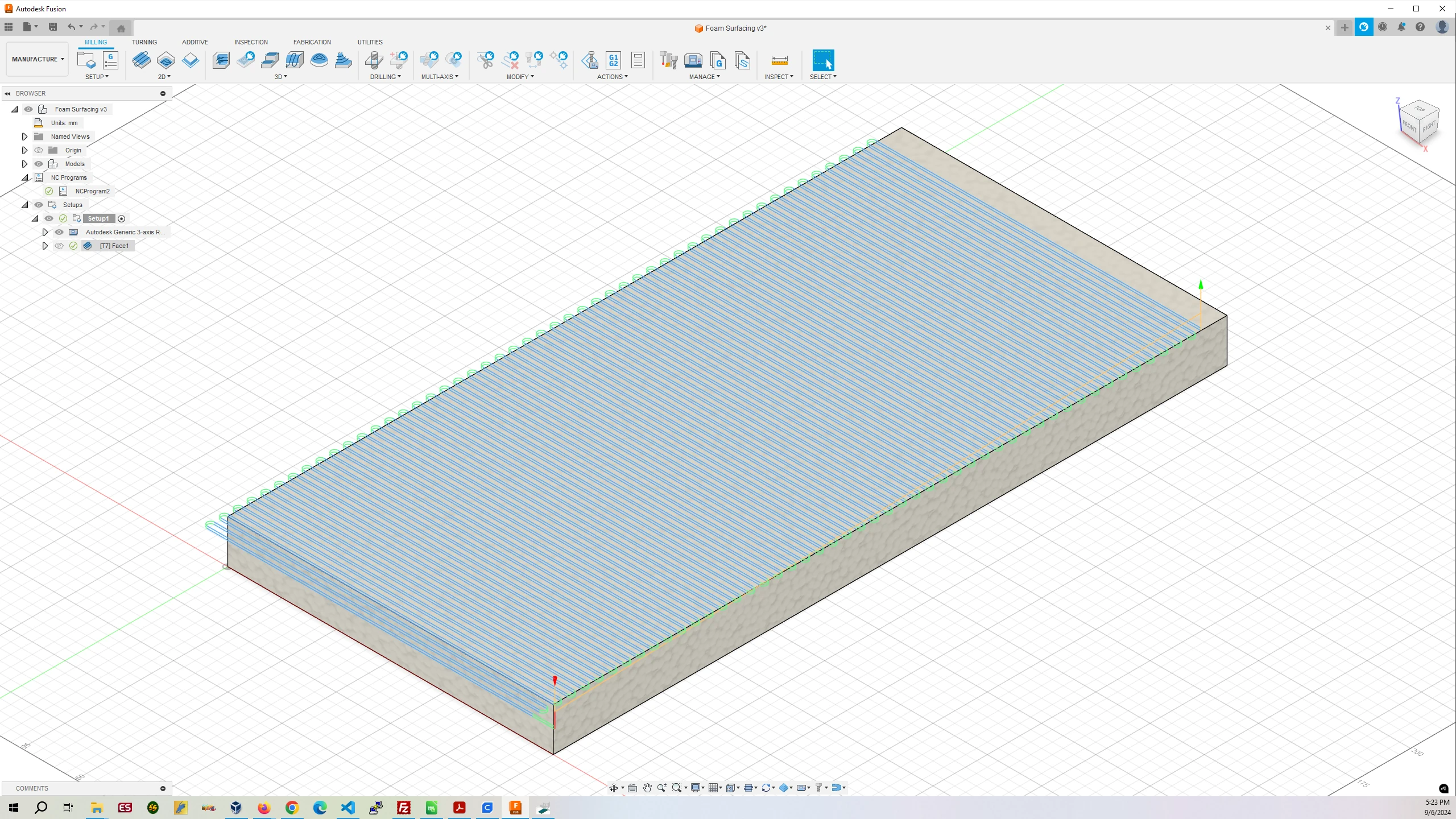
Surface the XPS Foam using the surfacing bit from the surfacing operation you performed on the Spoilboard for the MPCNC router. The surfacing bit is 1″ in diameter and the file XPS-Foam-Surfacing.gcode assumes you are using that bit. If you are using a different bit, open the XPS-Foam-Surfacing.f3z file in Autodesk Fusion 360 and change the bit used.
On the X-Axis place the clamps along the side to hold down the material. Make sure on the Y-Axis to place the left edge of the left most clamp at least 7″ from the left edge of the XPS Foam so the surfacing bit does not collide with the clamps. When it is finished remove the surfacing bit.
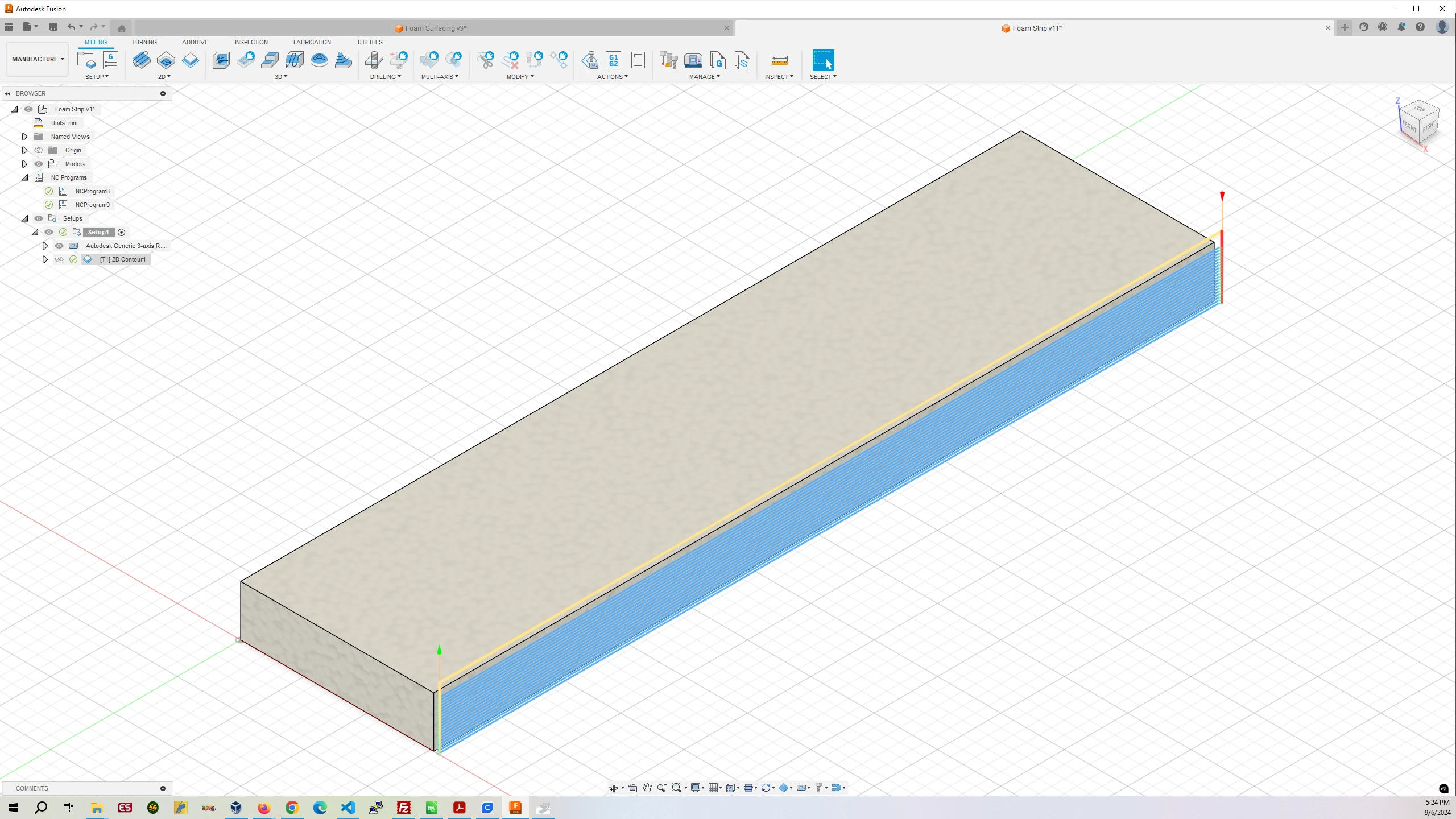
The file XPS-Foam-Cutting.gcode assumes you are cutting the foam with a 1/8″ milling bit. The X-Axis clamps can remain where they are from the surfacing operation. Place a Y-Axis clamp in between the left edge of the XPS Foam ensuring the right edge of the clamp is less than 3″ from the left edge of the XPS Foam. This will ensure the foam is clamped to the table and the milling bit doesn’t hit any clamps.
After the cutting operation is complete, remove the XPS Foam strip, move rest of the XPS Foam to the left up against the guide dowels, clamp the foam down and repeat the cutting operation. Two XPS Foam strips are needed to make the six Foam Plates.
Front
Back
4. Mill XPS Foam Plates 1 through 6
Download XPS Foam Milling Plates Files
The XPS Foam acts as a shock absorber when the free-fall object hits the cushion on the ground. It serves to encase the control and magnet objects as well as providing a space to hold the Arduino Nano 33 BLE Rev2, Powerboost 500 Basic, and Lipo battery together so they do not move.
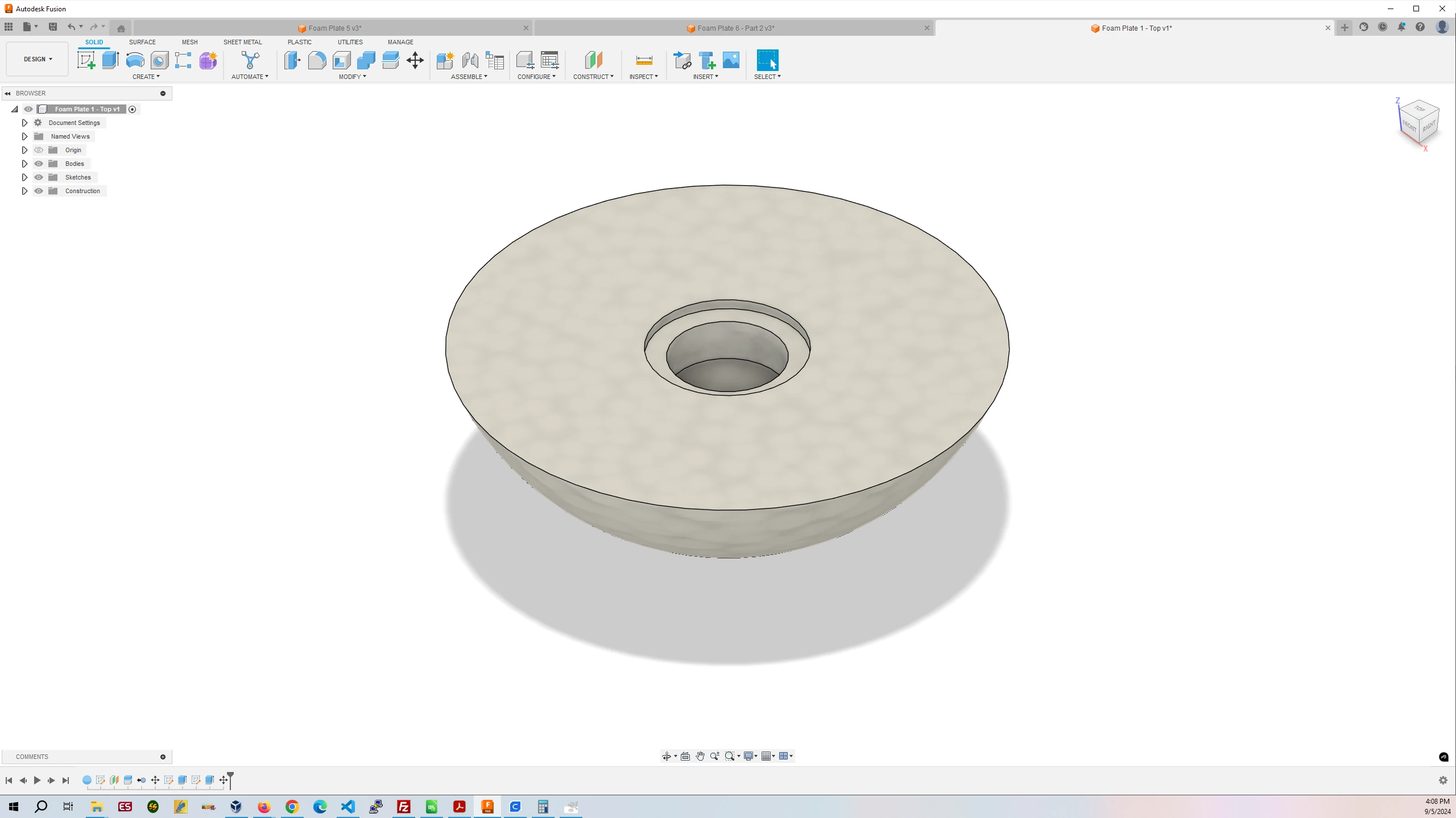
Foam Plate #1
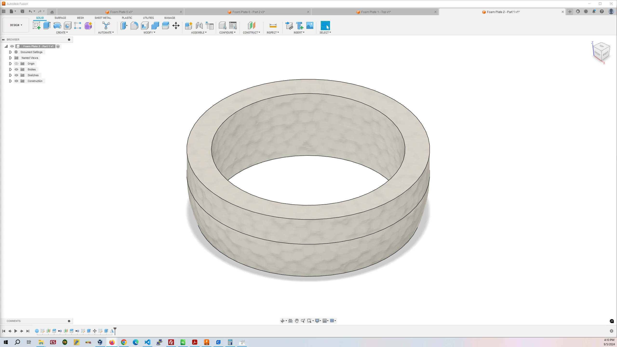
Foam Plate #2
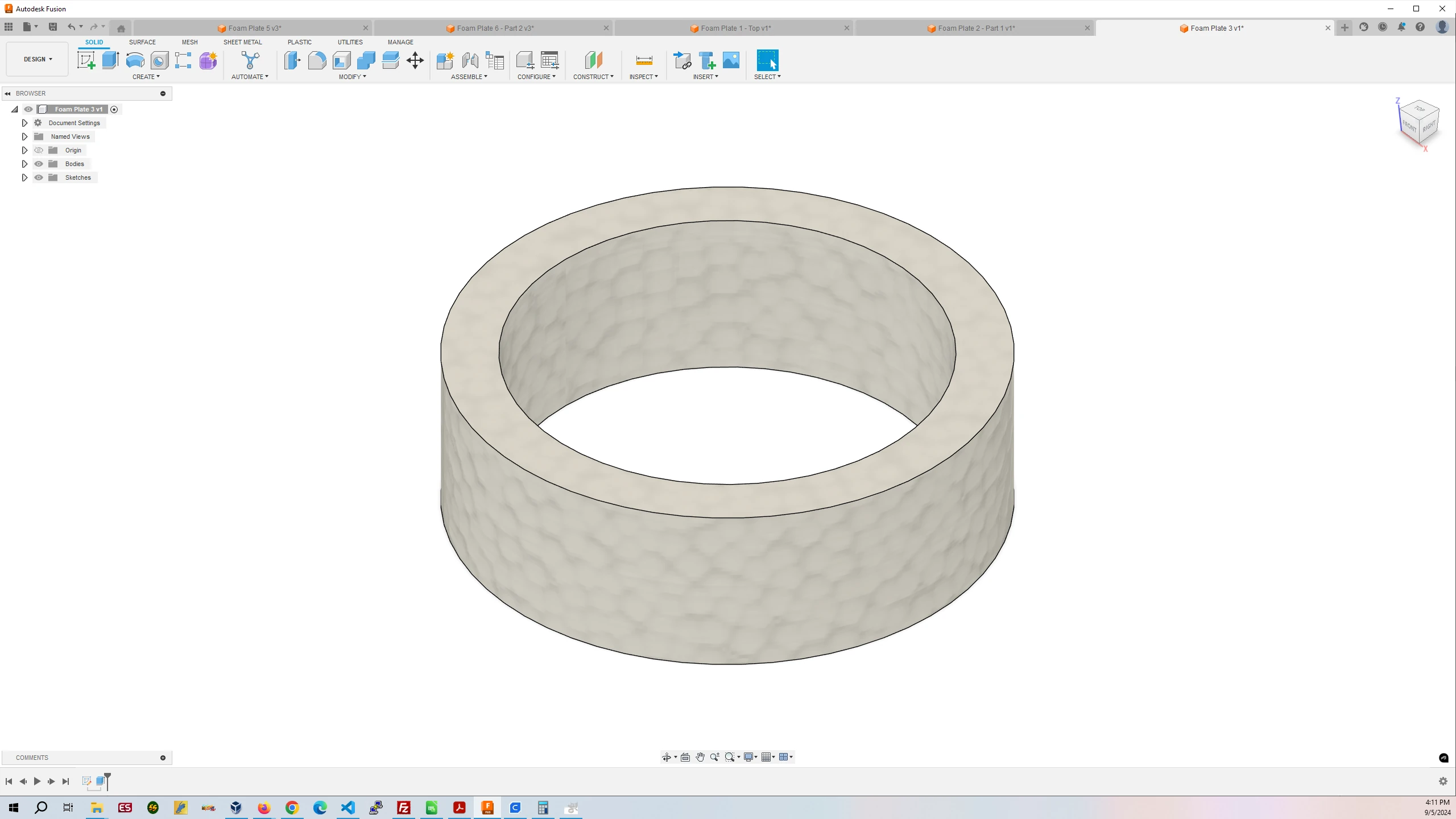
Foam Plate #3
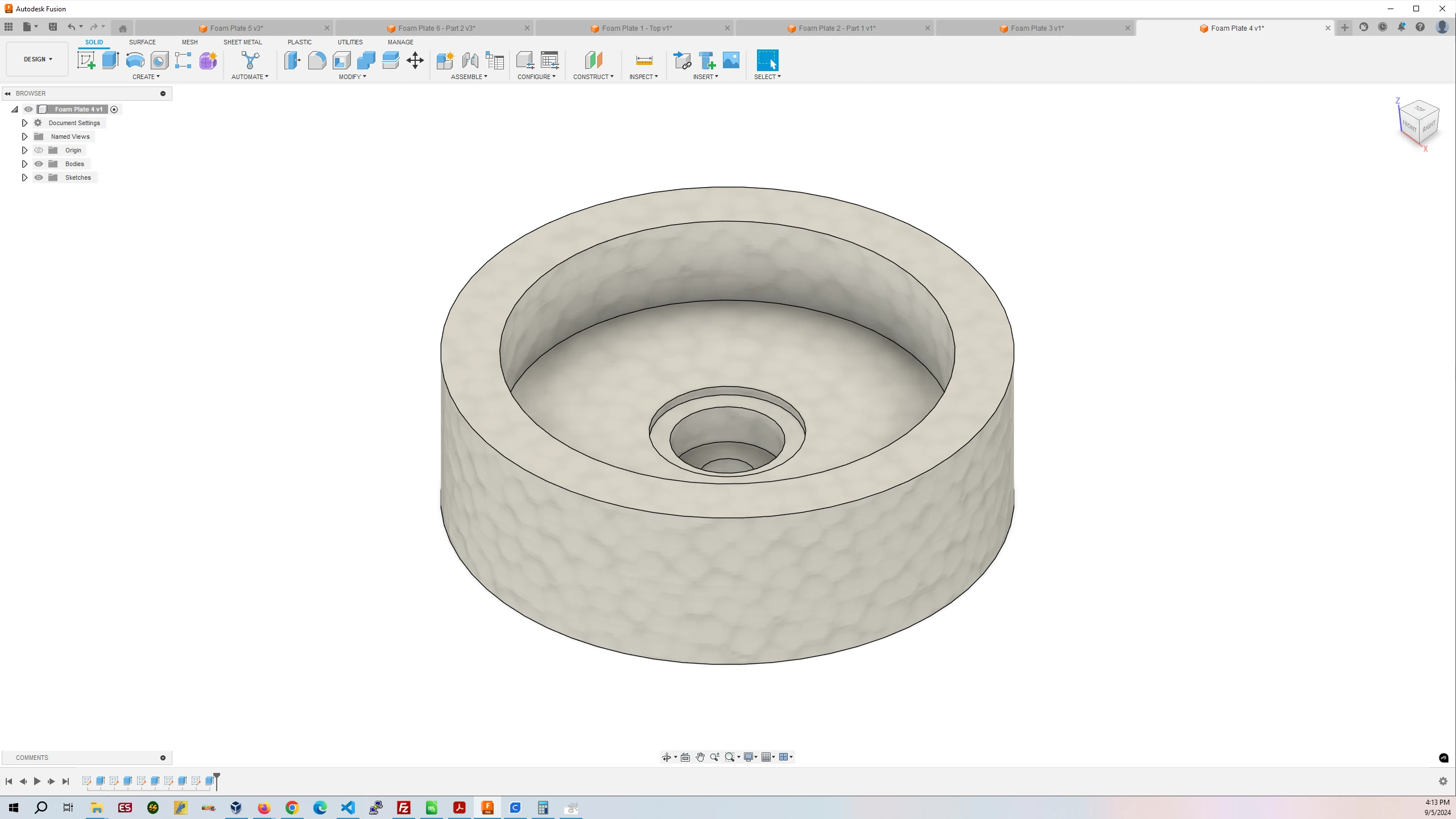
Foam Plate #4
Foam Plate #5
Foam Plate #6
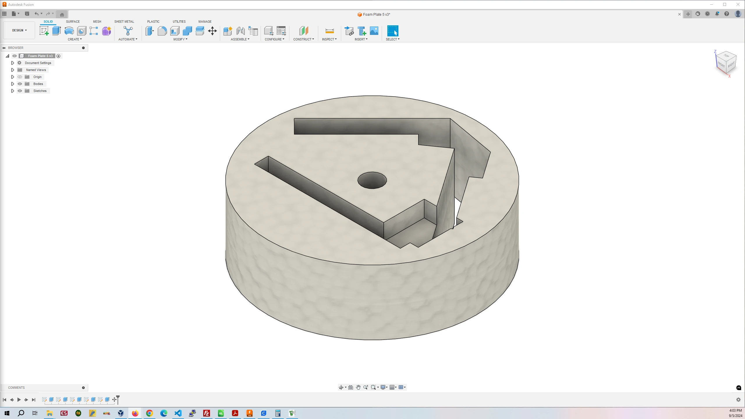
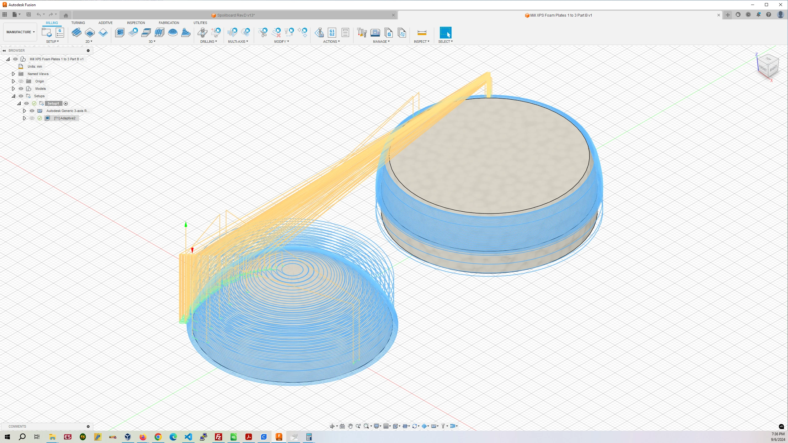
Step 1 will mill the pockets in Foam Plate 1.
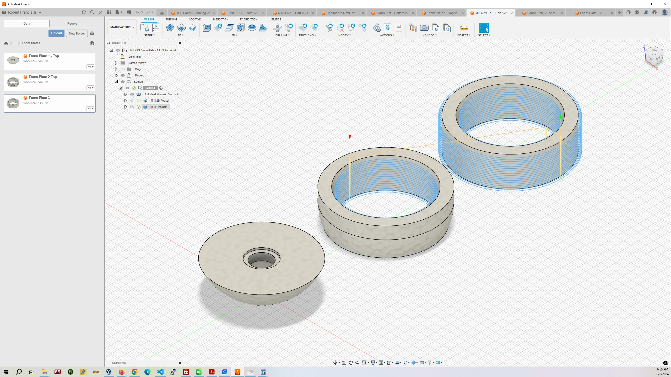
Step 2 will cut the inside out of Foam Plate 2 and 3 as well as cutting the outside of Plate 3.
Step 1 and 2 are accomplished by loading XPS-Foam-MIlling-Plates-1-3-Part-A.gcode into Octopi and running it. When complete remove the finished Foam Plate 3.
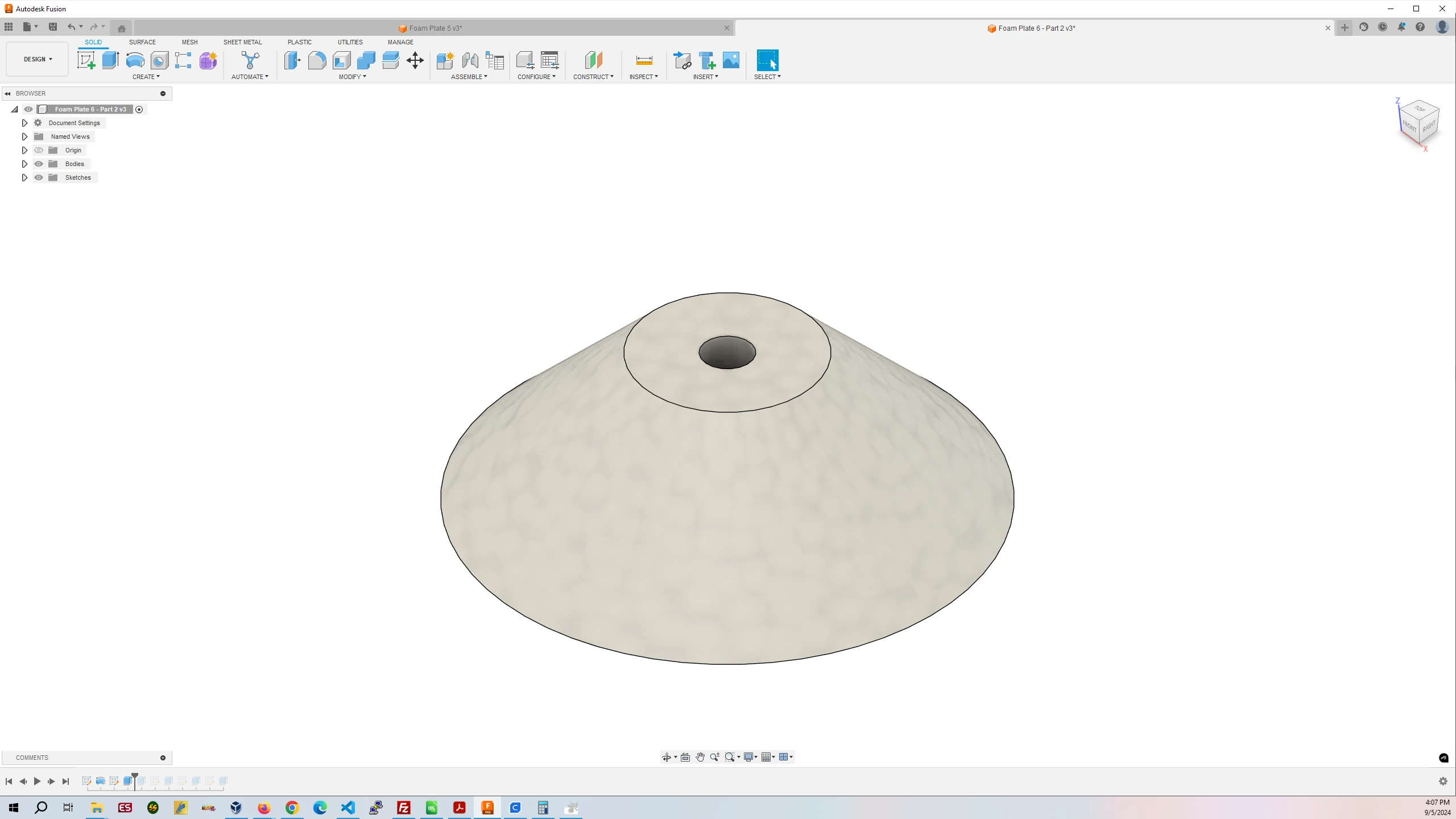
Step 3 requires you to flip over the foam strip. Adaptive Clearing will remove the material on this side and when finished Foam Plates 1 and 2 will be done.
Step 3 is accomplished by loading XPS-Foam-MIlling-Plates-1-3-Part-B.gcode into Octopi and running it. When complete remove the finished Foam Plates 1 and 2.
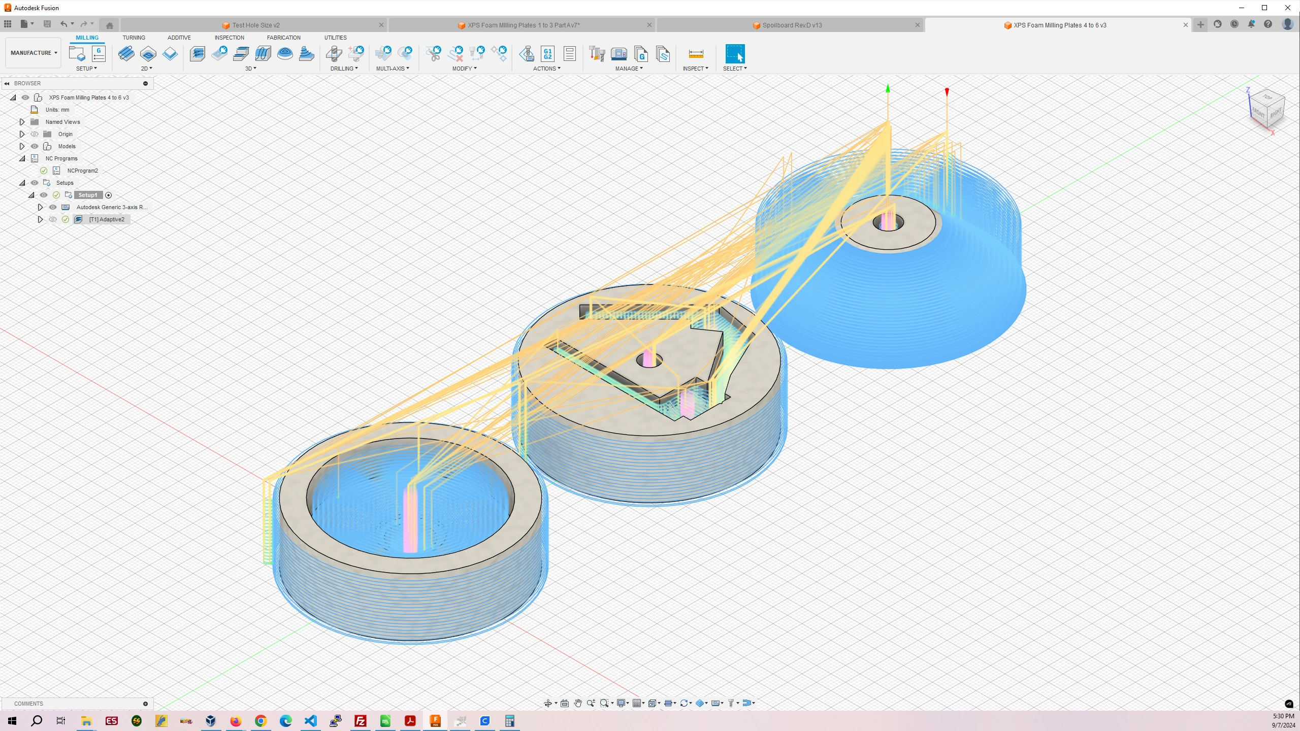
Step 4 requires you to place the second foam strip into the MPCNC. Adaptive Clearing will mill all the foam necessary to complete Foam Plates 4, 5, and 6.
Step 4 is accomplished by loading XPS-Foam-MIlling-Plates-4-6.gcode into Octopi and running it. When complete all Foam Plates are done and ready for use inside the plastic shell.
Step 1 – Top
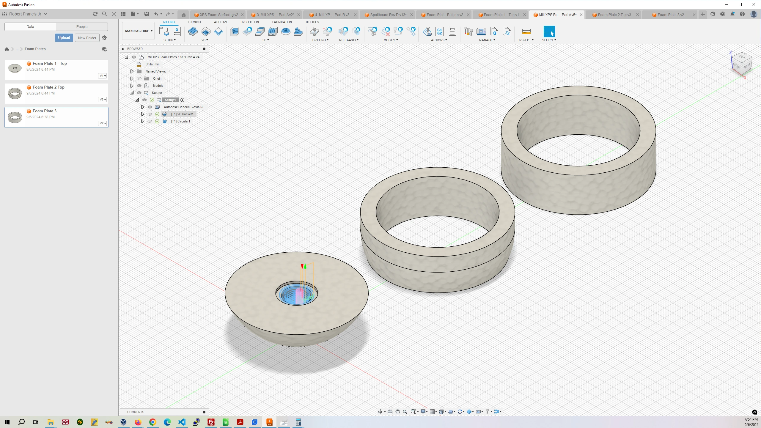
Step 2 – Top
Step 3 – Bottom
Step 4
5. Install the Arduino IDE and Required Libraries
In order to upload programs from your PC to the Arduino Nano you will need to install the Arduino IDE program available at the following address: https://www.arduino.cc/en/software
After it is installed you will need open the program and go to Sketch > Include Library > Manage Libraries
This will open a sidebar in the IDE.
Enter “IMU” in the search field.
Install the “Arduino_BMI270_BMM150” library.
Enter “HardwareBLESerial” in the search field.
Install the “HardwareBLESerial” library.
Go to Tools > Board: > Boards Manager
Enter “Mbed Nano” in the search field.
Install the “Arduino Mbed OS Nano Boards” library.
6. Test the Arduino Nano’s IMU Accelerometer
I ordered an Arduino Nano and the IMU unit would not initialize. Be sure to test the Arduino before soldering the Arduino to the PowerBoost. Connect the Arduino to your PC with a USB cable.
In the IDE go to Files > Examples > Arduino_BMI270_BMM150 and click on SimpleAccelerometer.
This will open the Accelerometer test program.
In the IDE go to Tools > Port: and select the COM Port that has (Arduino Nano 33 BLE)
In the IDE go to Tools and click on Serial Monitor to open the Serial Monitor tab in the program.
In the IDE then go to Sketch > Upload
After the program has compiled and uploaded to the Nano in the Serial Monitor tab it should print:
Accelerometer sample rate = 99.48 HzIt will then start printing and endless number of lines of the X, Y, and Z data from the IMU accelerometer.
7. Solder the Arduino Nano to the PowerBoost 500
How to solder is beyond the scope of this guide. If you do not know how to solder wires to circuit boards I recommend reading this informative guide with pictures to learn Soldering 101.
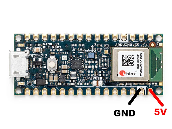
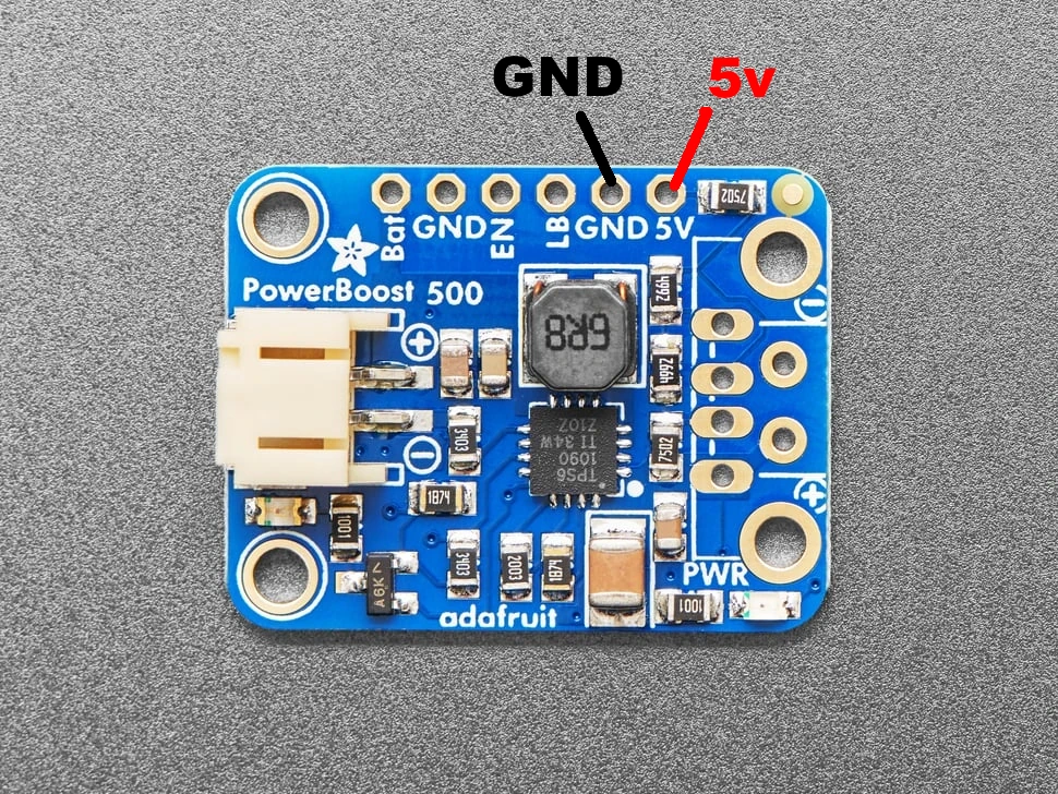
We will be using the the 24AWG wire from the materials list to connect the Arduino to the PowerBoost. I recommend using a black wire for Ground and Red wire for 5V.
As you can see in the image of Foam Plate 5 above there are parts milled all the way through the foam. Those are to hold the Arduino, the PowerBoost, and a Lipo battery that plugs into the PowerBoost. The small pocket not milled all the way through is where the wires between the Arduino and PowerBoost run connecting the two boards. The wires should be short and soldered from GND to GND and 5V to 5V.
Arduino Nano 33 BLE Rev2
PowerBoost 500 Basic
Now, when you begin free-fall tests you will attach the Lipo Battery to the PowerBoost 500 and tuck the three components into Foam Plate 5. The Lipo battery and PowerBoost will provide electricity to the Arduino and the Arduino’s onboard Bluetooth device will let you relay the Accelerometer data to your cellphone where it can be recorded and uploaded to the Cloud such as a Google Drive for further examination.
Make sure to keep the Lipo battery charged with the USB charger.
Your Magnet Free-Fall Object is complete.