IMU Calibration Device
In order to get the most accurate results from the IMUs you use in your free-fall object, they must be calibrated on all axes to generate the axes offset and scales values.
- Let’s Look at the Tool Requirements
- Let’s Look at the Material Requirements
- Print IMU Calibration Bed
- Insert Heat Insets into IMU Calibration Bed
- Setting the IMU Calibration Device
- Arduino IMU Calibration Code
- Calibrate Your IMU
1. Let’s Look at the Tool Requirements
| Item | Price | Quantity | Total | Location |
|---|---|---|---|---|
| Creality Ender 3 V3 SE 3D Printer | $199.00 | 1 | $199.00 | https://www.creality.com/products/creality-ender-3-v3-se |
| Hakko FX888D Soldering Iron | $113.72 | 1 | $113.72 | https://www.aliexpress.us/item/3256805523618695.html |
| Virtjoule Heat Set Insert Tips | $10.95 | 1 | $10.95 | https://www.amazon.com/dp/B08B17VQLD |
| Klein Tools 935DAG Electronic Level and Angle Gauge | $29.97 | 1 | $29.97 | https://www.amazon.com/dp/B07ZWW3BW5 |
| Grand Total | $353.64 | |||
2. Let’s Look at the Material Requirements
| Item | Price | Quantity | Total | Location |
|---|---|---|---|---|
| Elegoo PLA Filament 1kg | $16.19 | 1 | $16.19 | https://www.amazon.com/dp/B0BTGXDFRK |
| M4 Threaded Heat-Set Inserts Brass | $8.99 | 1 | $8.99 | https://www.amazon.com/dp/B09ZNX3ZCS |
| M4 Hex Socket Head Cap Metric Screws | $11.99 | 1 | $11.99 | https://www.amazon.com/dp/B0B4FP9PS4 |
| Grand Total | $37.17 | |||
3. Print IMU Calibration Bed
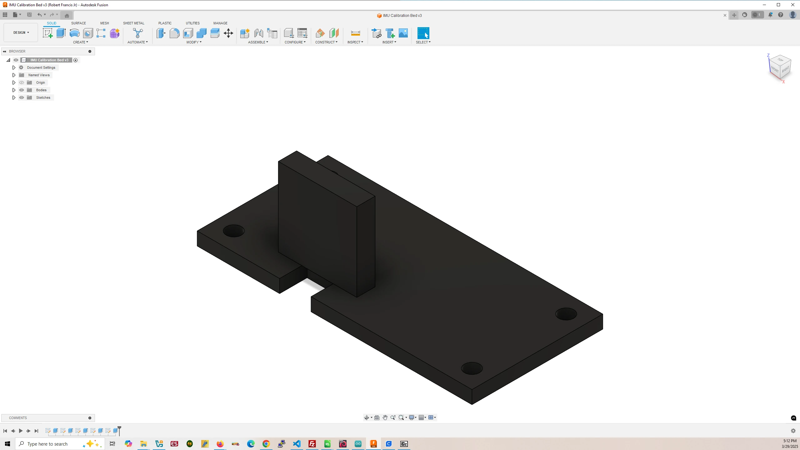
IMU Calibration Bed
Filament Used: 39g – 13.04m
Time to Print: 2 hours 8 minutes
- Ultimaker Cura Settings
-
- Walls > Wall Thickness > 2.0 mm
- Infill > Infill Density > 50.0%
- Support > Generate Support > None
- Build Plate Adhesion > Raft
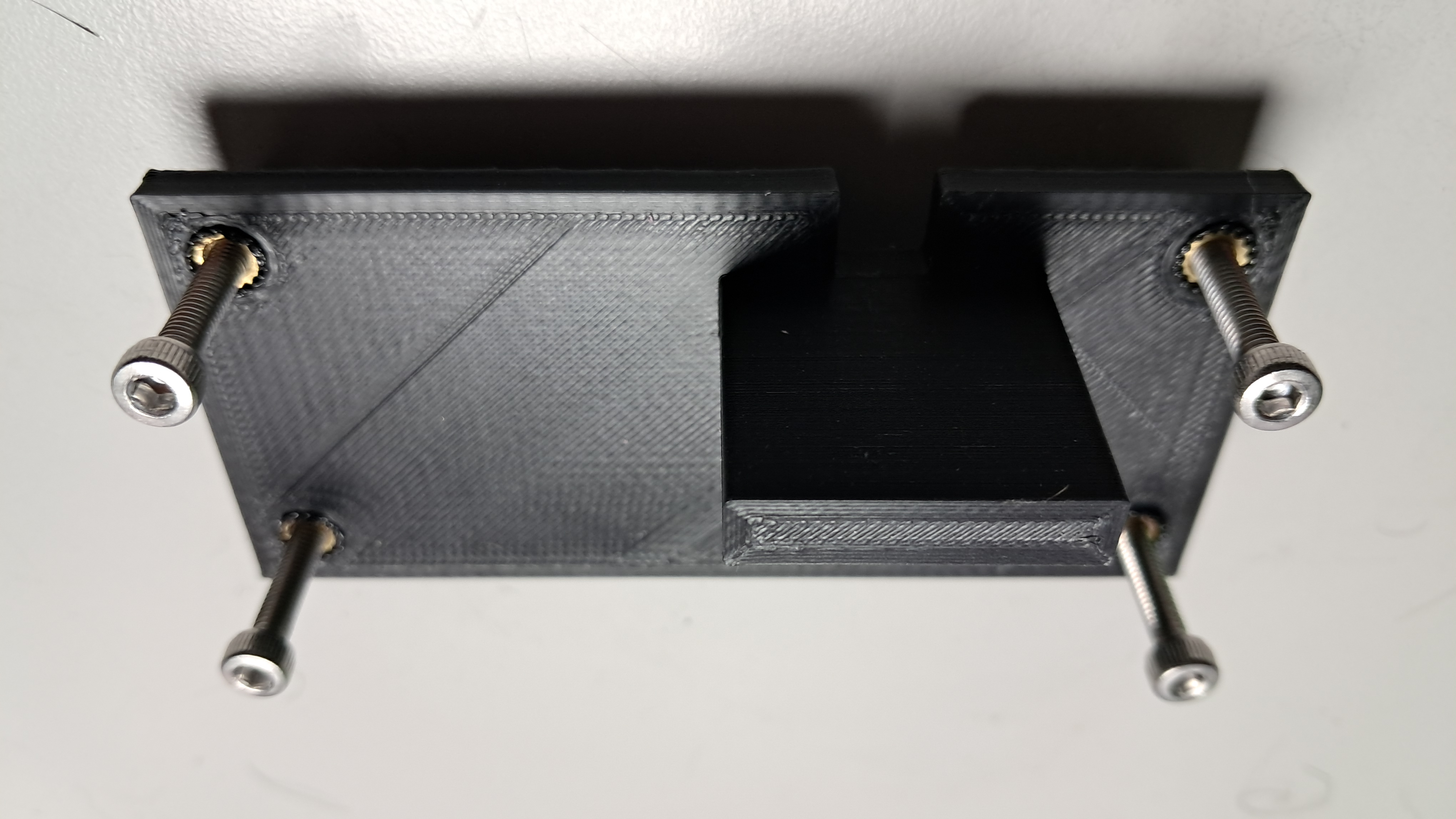
4. Insert Heat Insets into IMU Calibration Bed
You will need to unscrew the soldering iron tip and insert the M4 sized heat inset tip. Then turn on the soldering iron until it has reached operating temperature.
Then place the heat-set inserts onto the IMU Calibration Bed holes and insert the M4 heat inset tip into them and press down. The soldering iron will heat up the insets and pushing down on them will soften the plastic inserting the insets into the plastic.
5. Setting the IMU Calibration Device
Screw in the M4 Hex Socket Head Cap Metric Screws into the M4 heat insets. They will act as legs for the IMU Calibration Device.
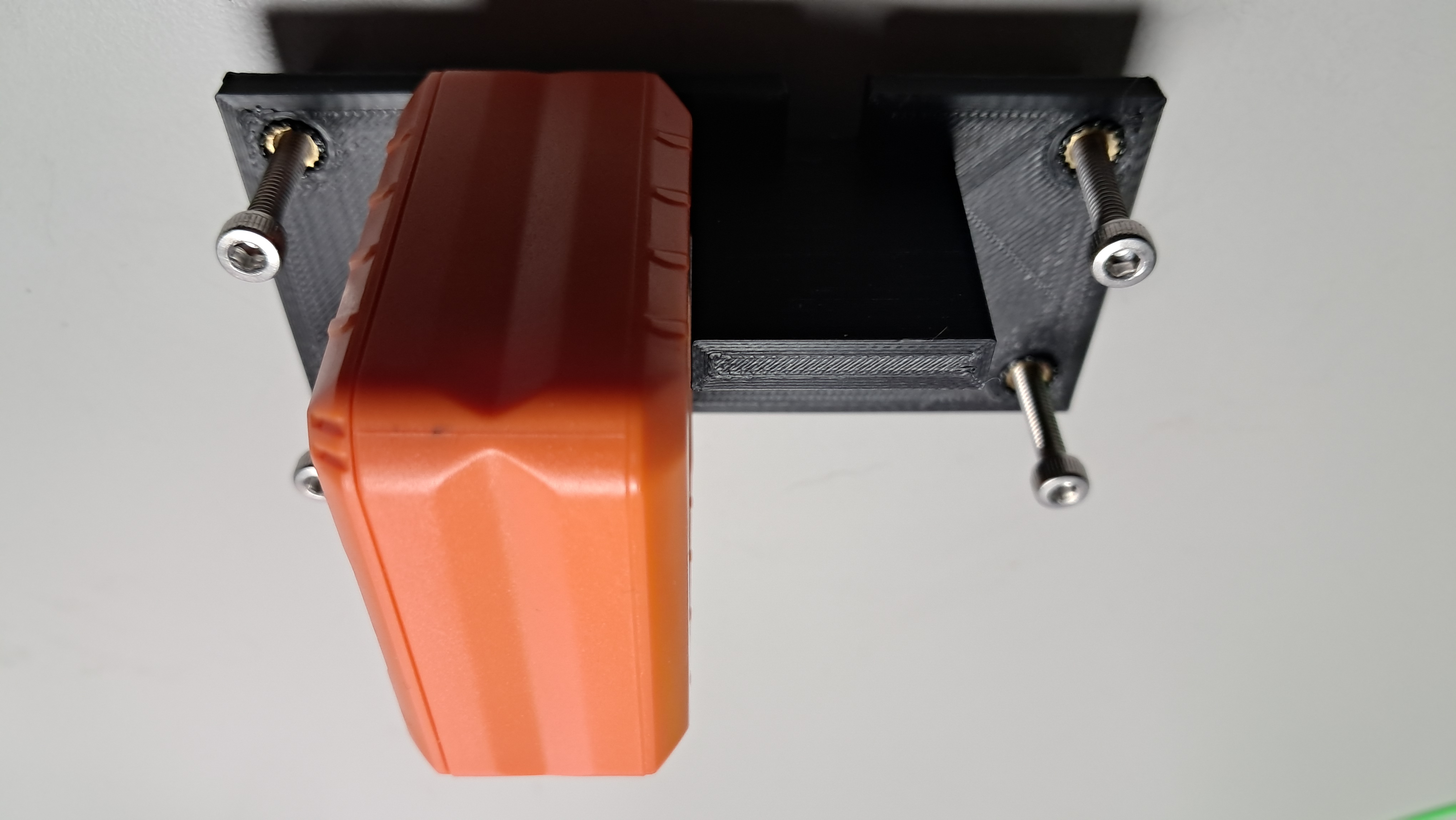
Place the IMU Calibration Device onto the table you will be using for calibrating your IMUs.
Place the electronic level onto the IMU Calibration Bed along the x-axis and fine tune the screws until the electronic level reads zero. Then place the electronic level onto the calibration bed along the y-axis and again fine tune the screws until the level reads zero.
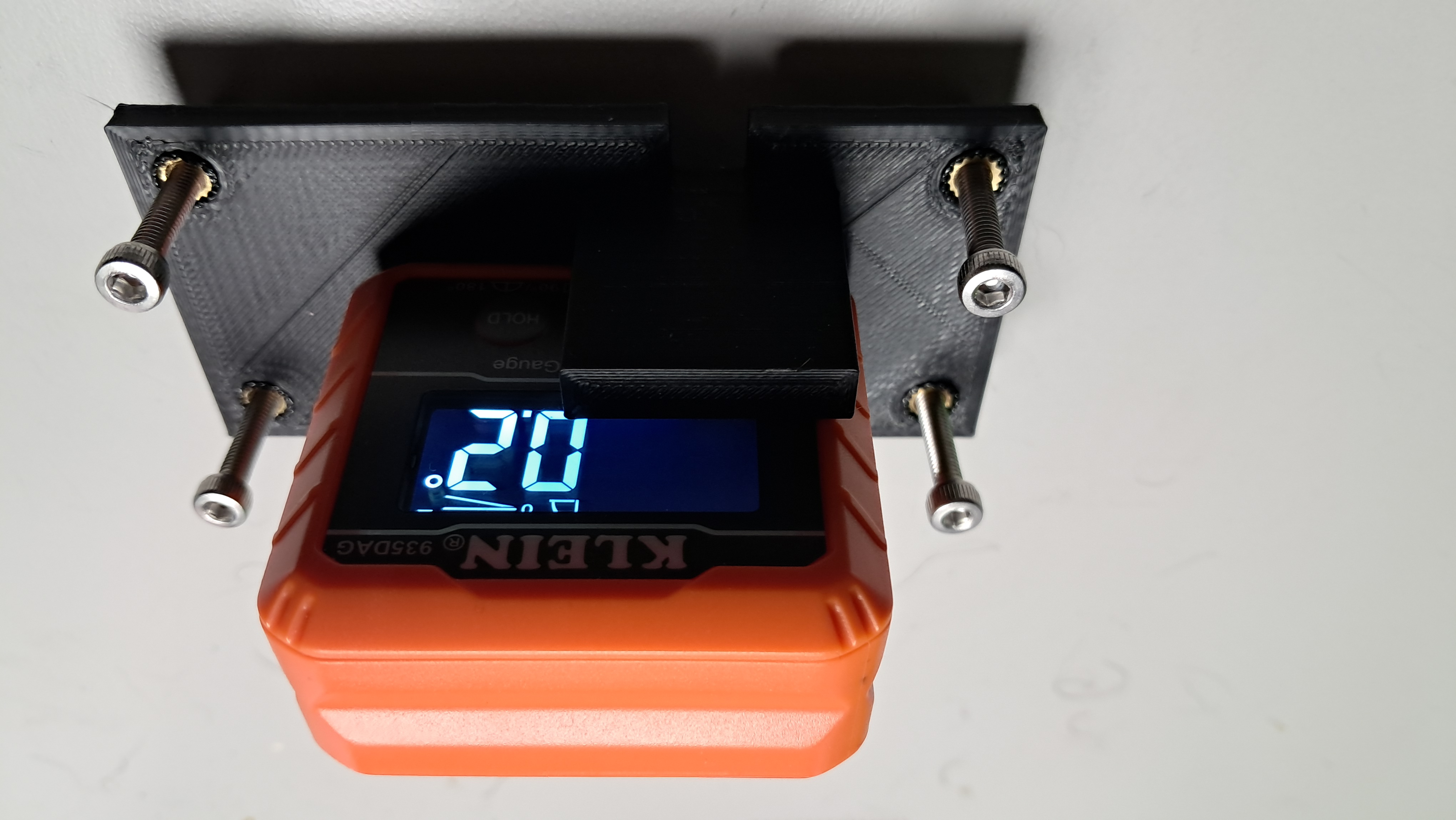
By using the level and screws you can ensure that the IMU Calibration Device’s bed is completely level which will ensure your IMUs have the highest accuracy when you calibrate them.
6. Arduino IMU Calibration Code
6.a. BMI270 Calibration Code
Download CalibrateBMI270 Arduino Code
The BMI270 is a part of the Arduino Nano 33 BLE Rev2 board. This IMU should be calibrated first before any wires are soldered to it which would skew the results when placed on the calibration bed.
6.b. ICM20649 Calibration Code
Download CalibrateICM20649 Arduino Code
6.c. ICM20948 Calibration Code
Download CalibrateICM20948 Arduino Code
6.d. ISM330DHCX Calibration Code
Download CalibrateISM330DHCX Arduino Code
6.e. LSM6DSO32 Calibration Code
Download CalibrateLSM6DSO32 Arduino Code
7. Calibrate Your IMU
With the code made for your IMU, upload it to your Arduino and follow the steps in the Serial Monitor. It will guide you in recording both polarities for the x, y, and z axis and once complete will provide you with the offset values and scaling values for each axis which you will need to write down and use in your free-fall object Arduino code when conducting experiments.