Magnet Free-Fall Experiment
Mark 10
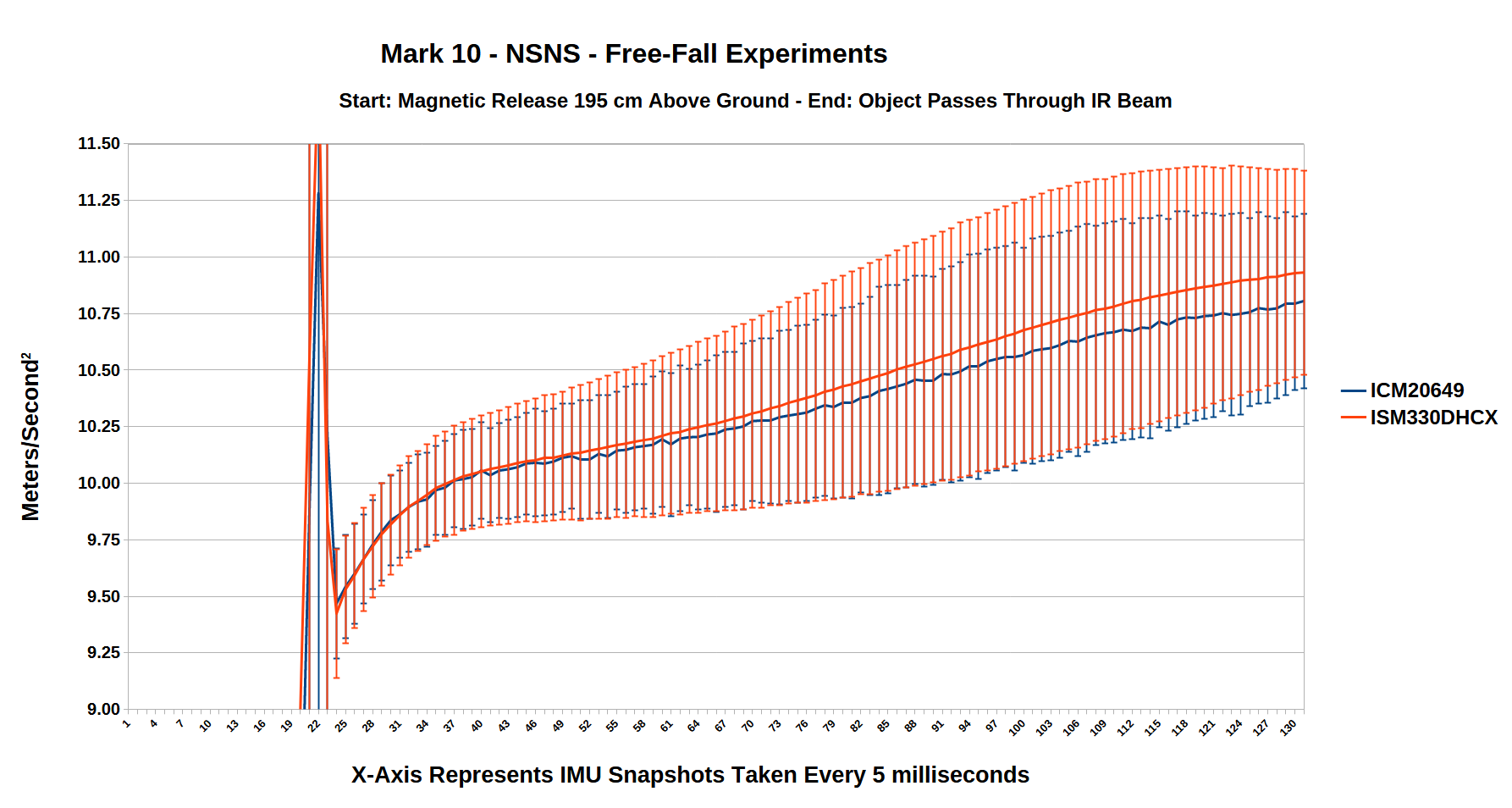
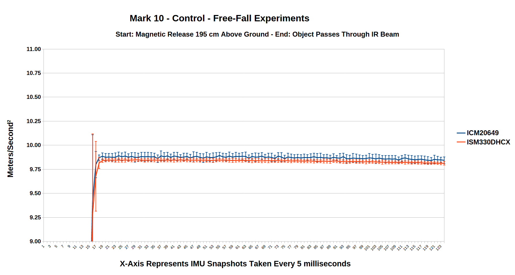
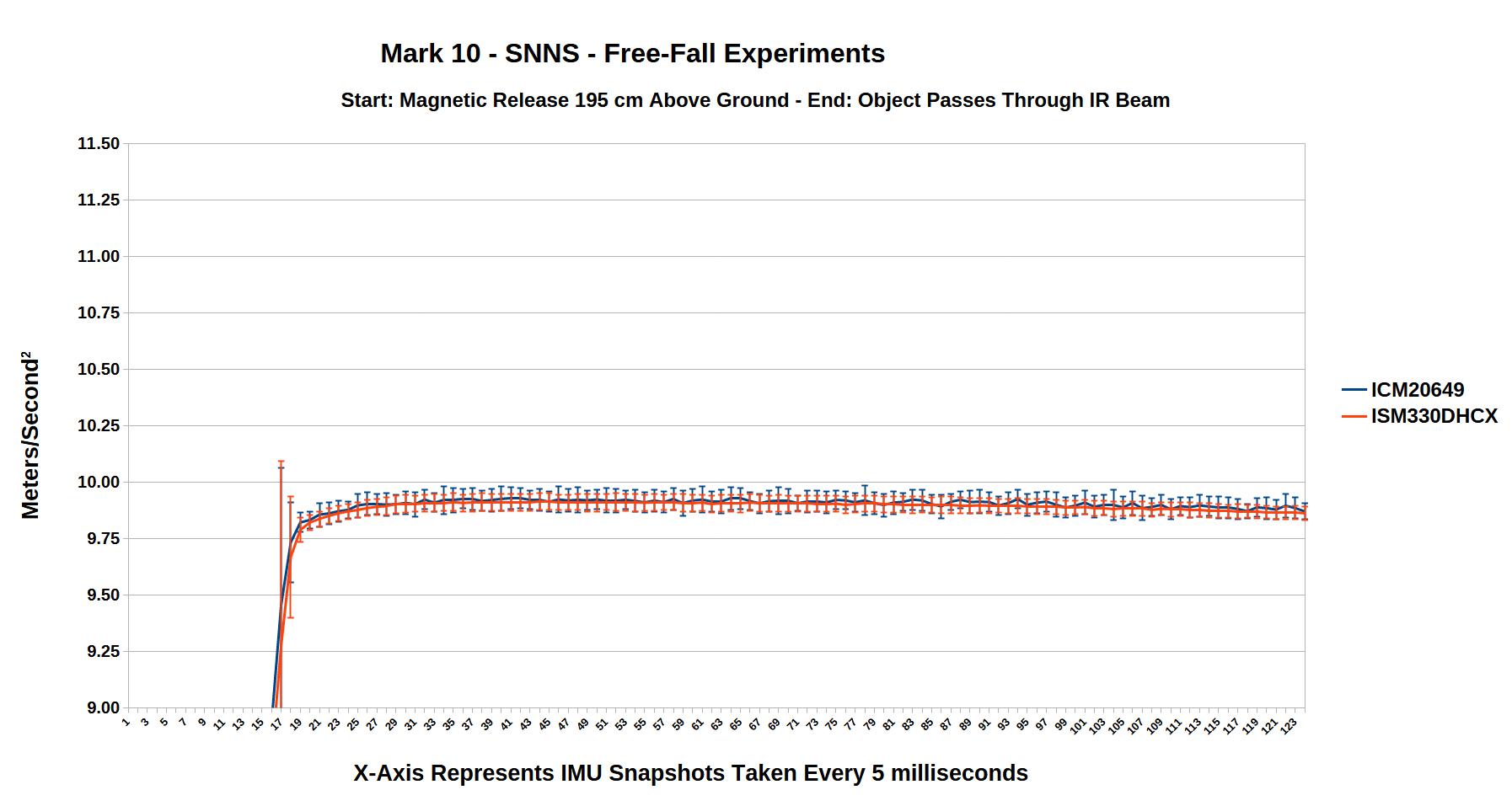
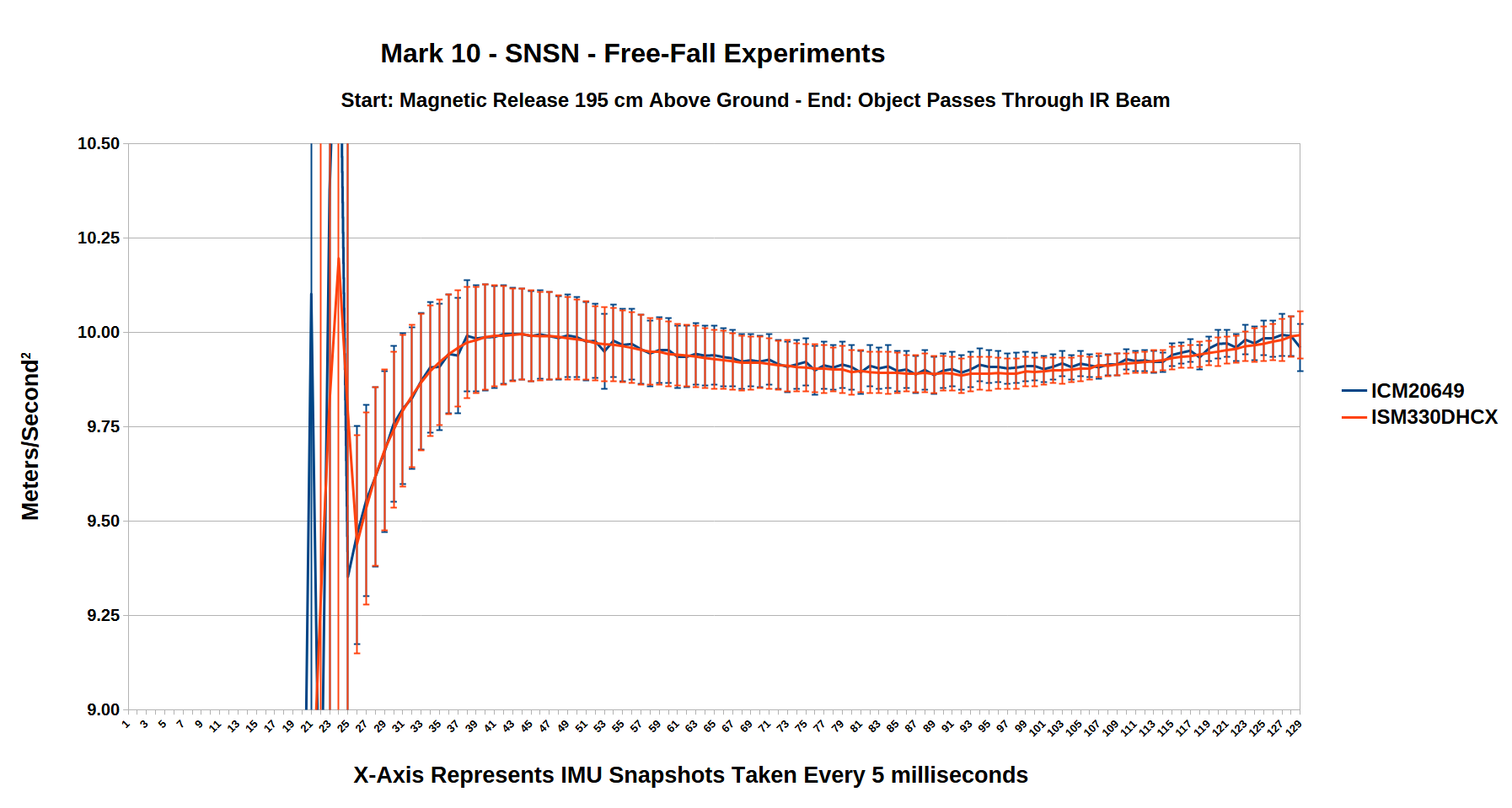
The Mark 10 free-fall experiment is the first to use two IMUs (ICM20649 and ISM330DHCX) inside the free-fall object along with a SensorFusion library to fuse accelerometer and gyroscope data with a Mahony filter. Each IMU is calibrated with my self-built calibration device and calibration code with the offset and scale values used in the free-fall object code. The back shells have a steel fender washer super-glued to them in order to magnetically couple with a solenoid coil at the top of the drop device used for computer controlled dropping of the free-fall objects.
Results
- Grade: A
-
- Max Acceleration: 11.93 m/s2
- Average Acceleration: 10.9316 m/s2
- Std Deviation: 0.451
- ANOVA: Pr(>F) <2e-16
- Magnet: 2 x N42, 2″ OD, 1/4″ ID, 1″ thick
- Drop Height: 1.95 meters
- IMU: ICM20649 & ISM330DHCX
- Calibration: Offsets and Scaling
- Filter: Mahony
- Drop Method: Computer
- Replication Warranted: Yes

How Can You Help?
I am eager to spread the knowledge of inertial mass reduction technology for its own sake but it might very well also be a path to faster than light propulsion technology. Diffusing this knowledge through academia and the world of science will only happen when many people have replicated this experiment, so many that it gets covered in science journals and science oriented popular media which is why I am willing to take on this work to assist you in assisting me in my goal.
For those looking to replicate this experiment but lack access to a 3D printer and CNC router I can 3D print the plastic shells, mill the XPS foam on my CNC router, and solder the electronics together. I can then ship them to your address for the cost of materials and shipping.
That said, the drop device will need to be built by you and requires a circular saw, miter saw, or radial arm saw to cut the 2x4s as well as a drill.
Then, all you need to do is buy the magnets, assemble them into the shell, conduct the free-fall experiments, record your data, and publish your data for the world to see.
Contact me if you are interested in such an arrangement. 🙂
me@robertfrancisjr.com
- The Objects to be Tested
- Let’s Look at the Tool Requirements
- Let’s Look at the Free-Fall Object Materials
- Let’s Look at the Drop-Device Materials
- Mill EPS Foam Magnet Container Plates
- Manufacture Free-Fall Object Components
- Configure the Free-Fall Object’s Electronics
- Manufacture Drop-Device Components
- Assembling the Coupled Magnets
- Assembling the Free-Fall Object
1. The Objects to be Tested
Five objects will be tested in this experiment:
- A Control object composed of fender washers.
- NS/NS object composed of two magnets attractively coupled being dropped in the direction of their north pole to south pole.
- SN/SN object composed of two magnets attractively coupled being dropped in the direction of their south pole to north pole.
- NS/SN object composed of two magnets repulsively coupled.
- SN/NS object composed of two magnets repulsively coupled.
2. Let’s Look at the Tool Requirements
To Buy or Rent?
If you lack any of these tools below they are usually available at a local Maker Space. It depends how far you want to go. If you are merely replicating my experiments the you can likely get buy signing up for a few months to a local Maker Space and using their tools. They likely have educational guides on how to use them as well.
If however you will be modifying CAD drawings and making custom parts then it might make sense to buy these tools. That is what I ended up doing as traveling 60 miles a day back and forth to the Maker Space just didn’t make sense for me.
You will need:
- 3D Printer
- CNC Router
- Soldering Equipment
- Circular Saw, Guide Fence, Squeeze Clamps and Table, or Miter Saw, or Radial Arm Saw
- Tap and Die Set
- Wire Strippers
- Small Screw Driver Kit
Important note, I included .gcode files for the 3D printed plastic shell parts and for the milled foam encasement pieces. The .gcode files are specifically made for the Creality Ender 3 V3 SE and for the MPCNC Primo router respectively. In the 3D printer .zip files I also included Universal Cura Project .3mf files for those who use Ultimaker Cura along with plain .stl files for everyone else. For the milled foam pieces I included Autodesk Fusion 360 .f3z files along for importation into Fusion 360 where you can then generate the specific .gcode files for your CNC router.
A final option for those looking to conduct this experiment is to have me 3D print the plastic shell, mill the XPS foam on my CNC router, and solder the electronics together. I can then ship them to your address for the cost of materials and shipping.
I am eager to spread the knowledge of inertia reduction which will only happen when many people have replicated this experiment which is why I am willing to take on this work to assist you in assisting me.
3. Let’s Look at the Free-Fall Object Materials
4. Let’s Look at the Drop-Device Materials
5. Mill EPS Foam Magnet Container Plates
Download EPS Foam Milling Files
The magnets are too strong and dangerous to just be left lying around on a table or in a drawer or something. I recommend buying some EPS foam, milling it to fit the assembled magnet object, and a cardboard box to place it all in, finally taping the box shut when not in use.
EPS Foam Step #1
EPS Foam Step #2

EPS Foam Step #3
6. Manufacture Free-Fall Object Components
6.a. Print the Free-Fall Object Shell
Download Mark 10 – Plastic Shells
The plastic shell has a bullet shaped nose and the shell itself is 1.5mm thick. There are eight tubes on the front of the shell, half inside and half outside the front shell for improved aerodynamics. The tubes need to have threads cut into them with an M3x0.5 tap from a tap and die set. The back shells have eight holes for fastening the backs to the front with M3 x 20mm Stainless Steel 316 screws.
Using super glue, glue a 1 1/4″OD x 1/4″ID steel fender washer to the recessed portion of the Back Shell for magnetic coupling to the solenoid coil in the drop-device.
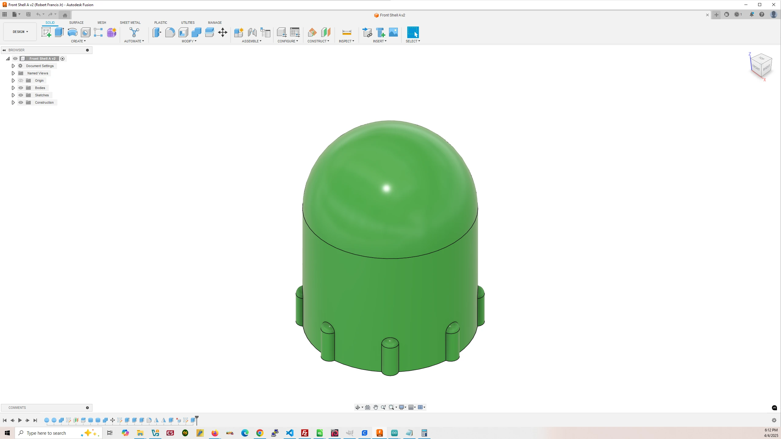
Mark 10 – Front Shell
Filament Used: 70g – 23.38m
Time to Print: 6 hours 31 minutes
- Ultimaker Cura Settings
-
- Walls > Wall Thickness > 2.0 mm
- Infill > Infill Density > 50.0%
- Support > Generate Support > Tree
- Build Plate Adhesion > Raft
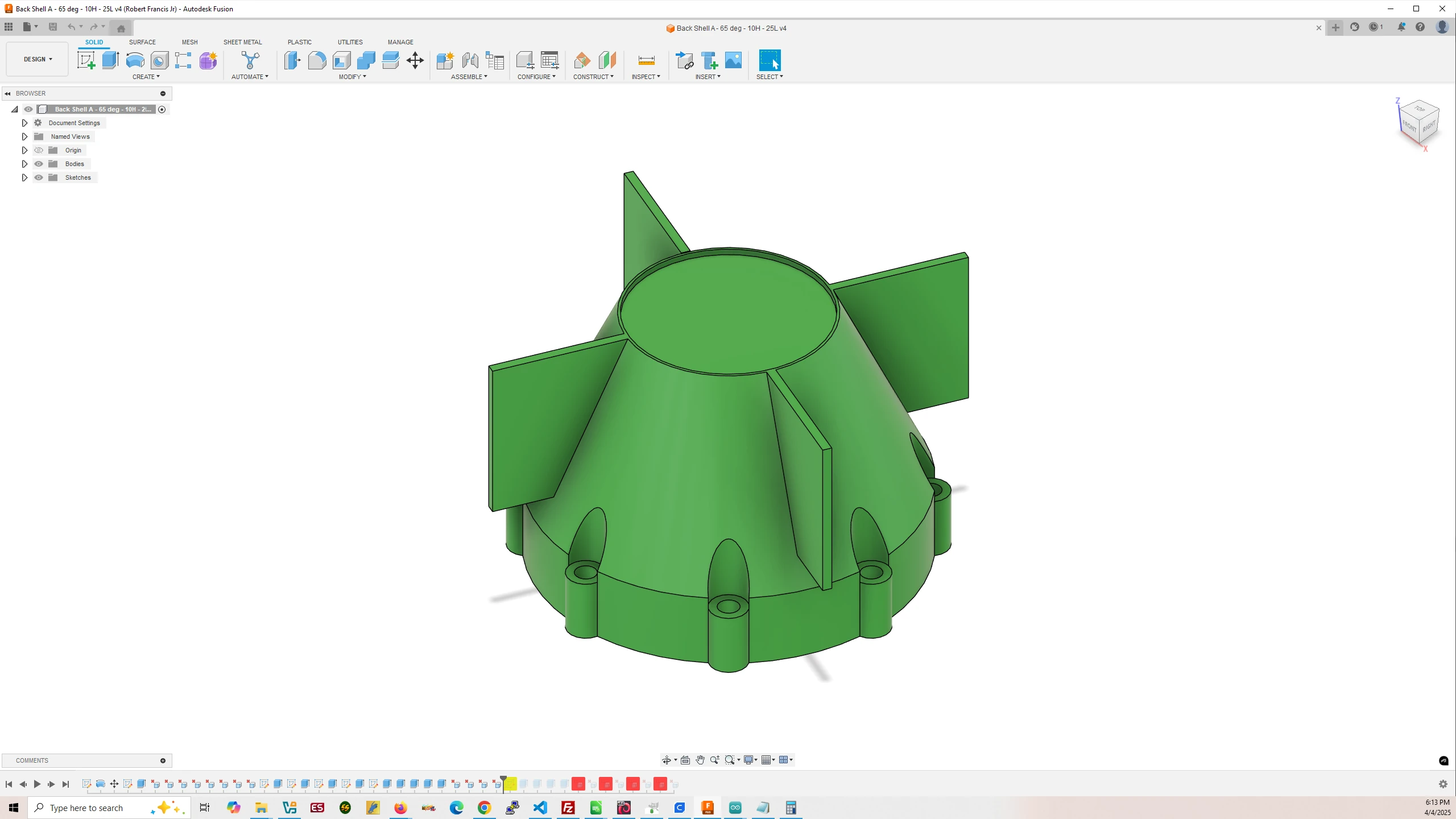
Mark 10 – Back Shell
65 Deg – 10H – 25L
Filament Used: 31g – 10.37m
Time to Print: 2 hours 23 minutes
- Ultimaker Cura Settings
-
- Walls > Wall Thickness > 2.0 mm
- Infill > Infill Density > 50.0%
- Support > Generate Support > Tree
- Build Plate Adhesion > Raft
6.b. Cut and Mill the Free-Fall Object Foam
6.b.i. Cut the Foam to Width
Download XPS Foam Cutting Files
The XPS foam in the materials list from Home Depot is 2’x2′. I would recommend cutting the foam into four 1ft x 1ft blocks that can then be cut with precision into 90mm width strips on your CNC router using the above files. If you are using an MPCNC router you can use the included .gcode file otherwise you will need to import the .f3z file into Autodesk Fusion 360 and generate the .gcode file for your specific CNC router. The files assume you calibrate your milling bit off of the spoilboard, NOT the top of the material being milled.
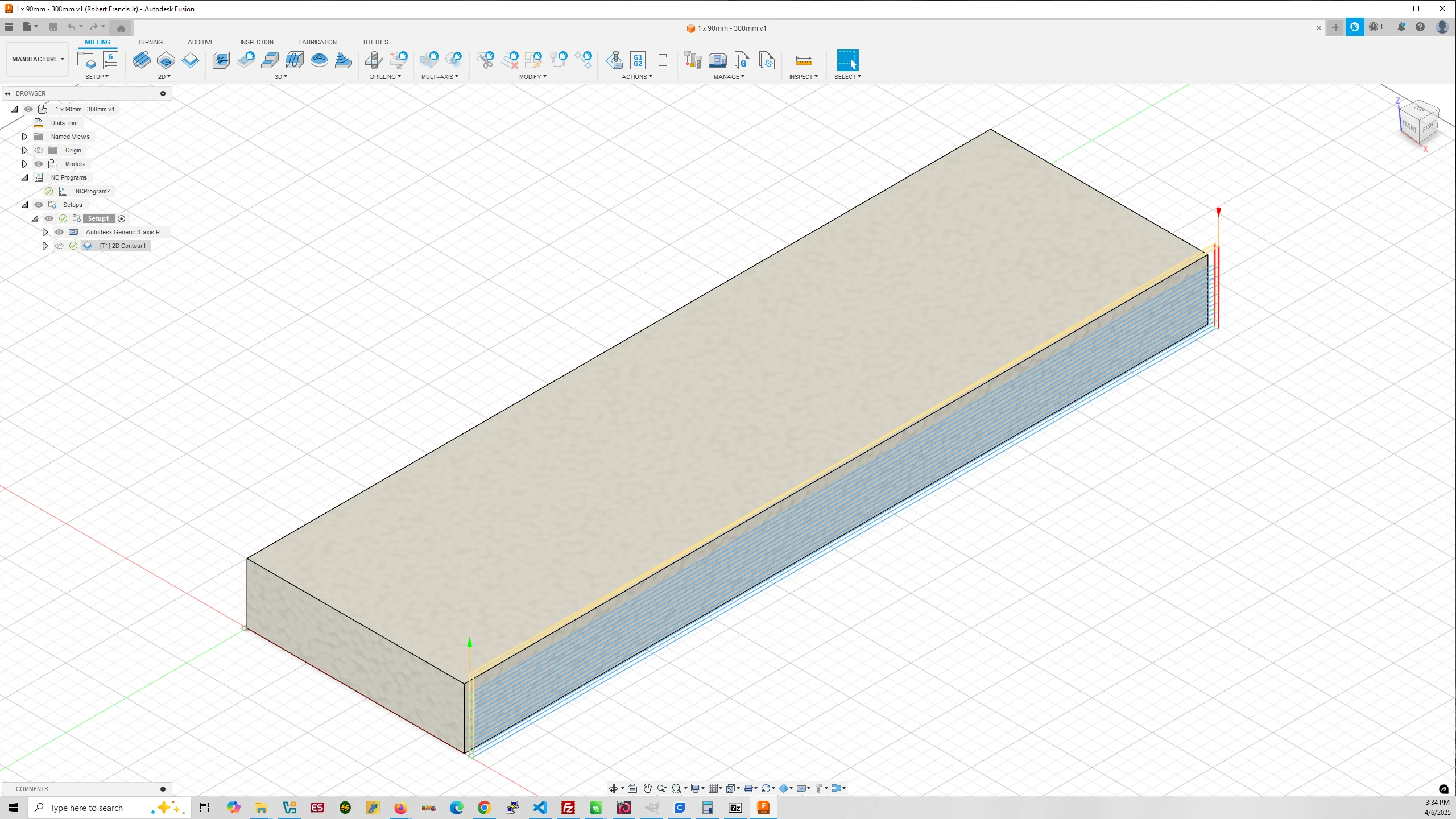
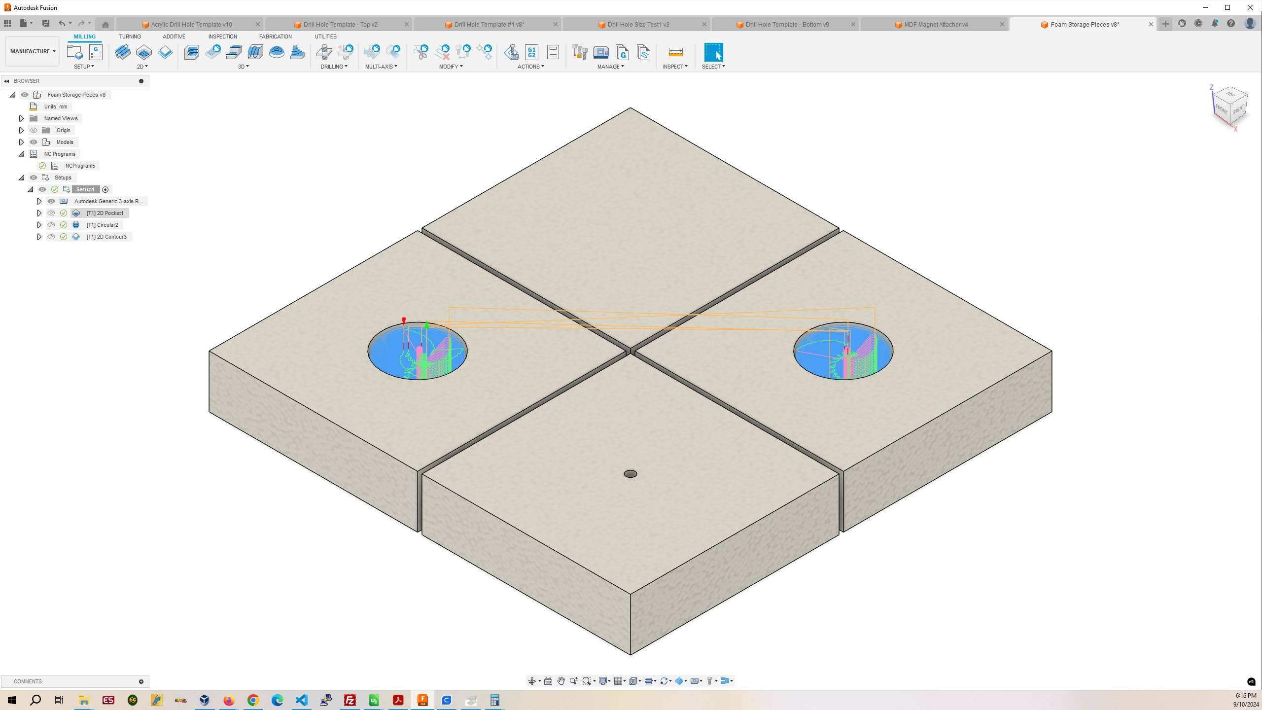
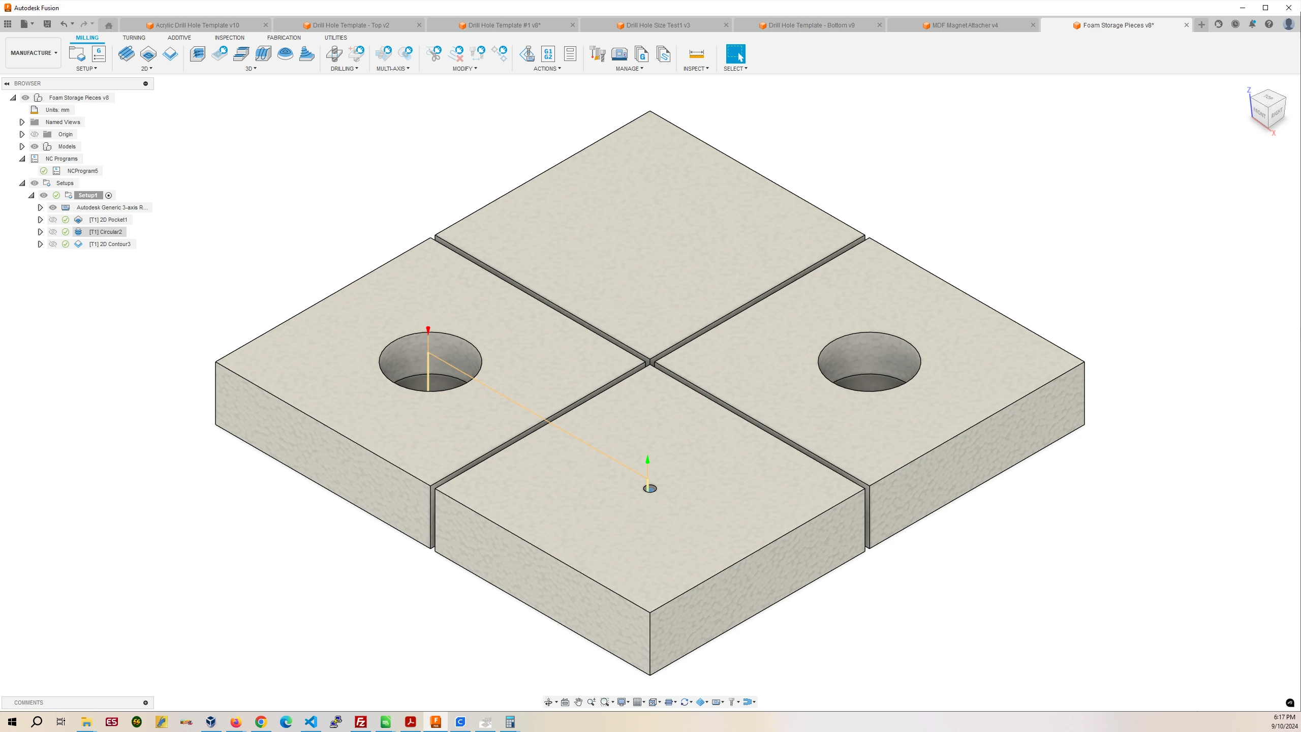
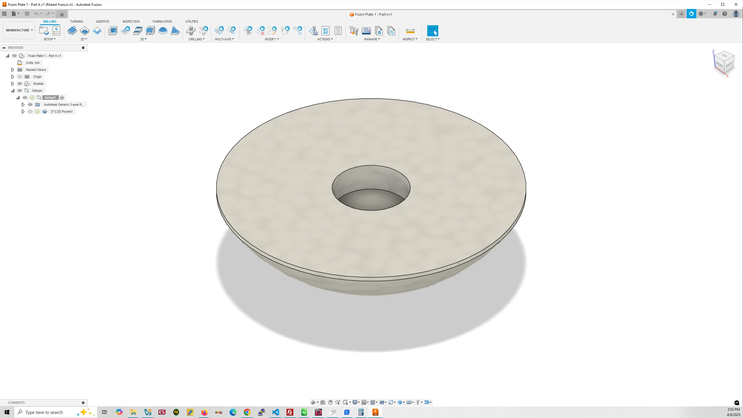
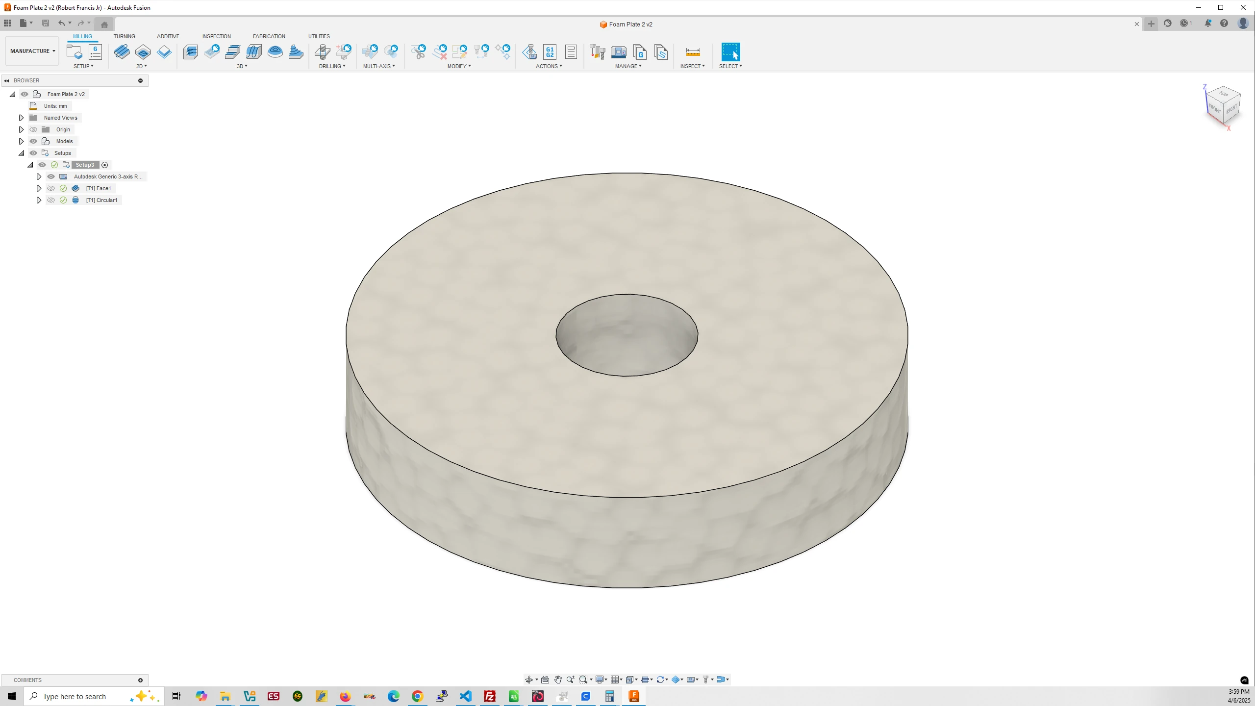
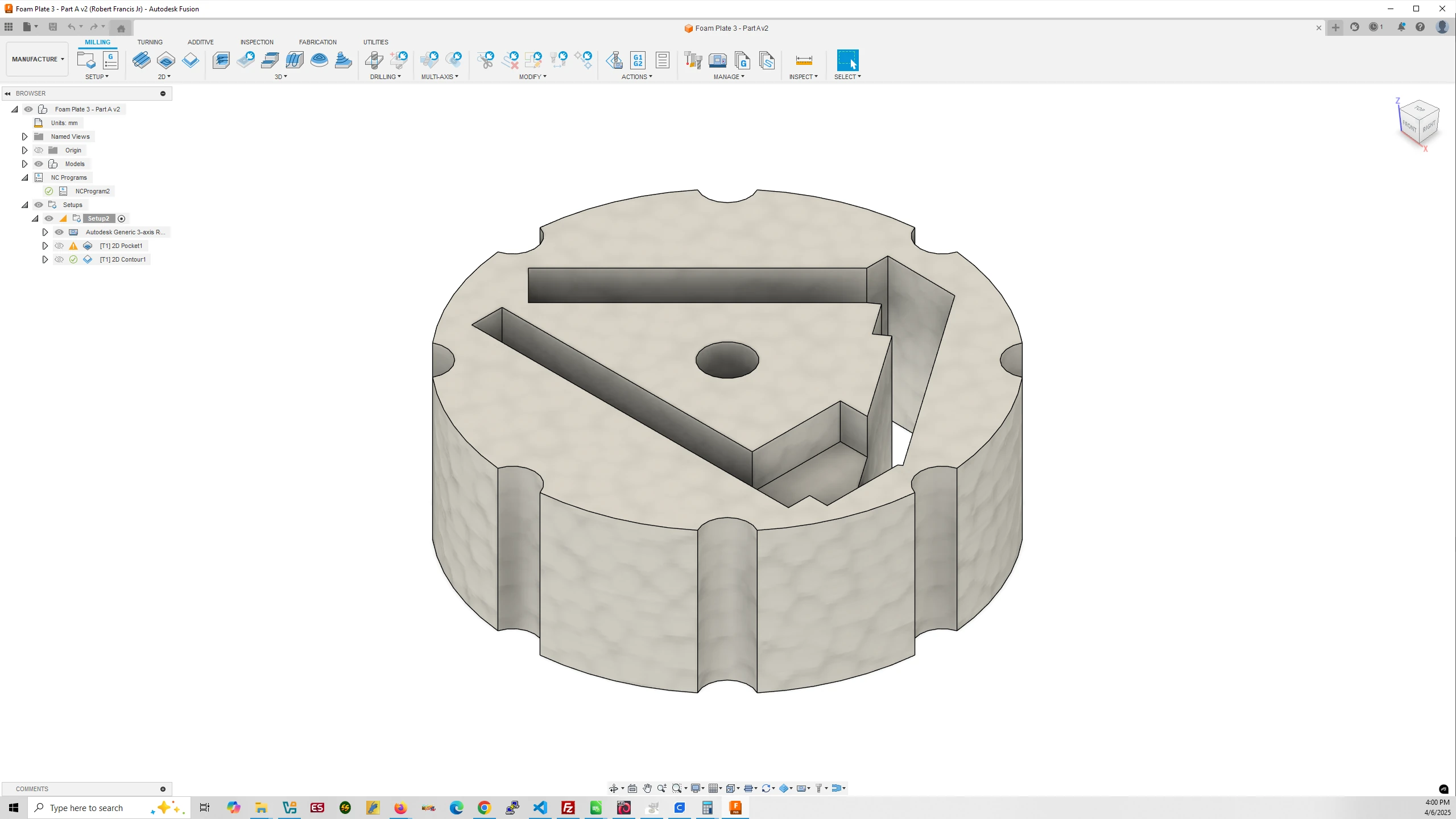
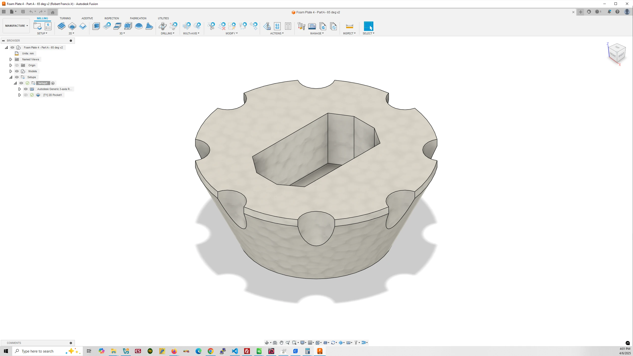
6.b.ii. Mill XPS Foam Plates
Download Mark 10 – Foam Operation Files
The XPS Foam acts as a shock absorber when the free-fall object hits the cushion on the ground. It serves to encase the control and magnet objects as well as providing a space to hold the Arduino Nano 33 BLE Rev2, Powerboost 500 Basic, Lipo battery, and IMUs so they do not move.
Foam Plate #1
Foam Plate #2
Foam Plate #3
Foam Plate #4
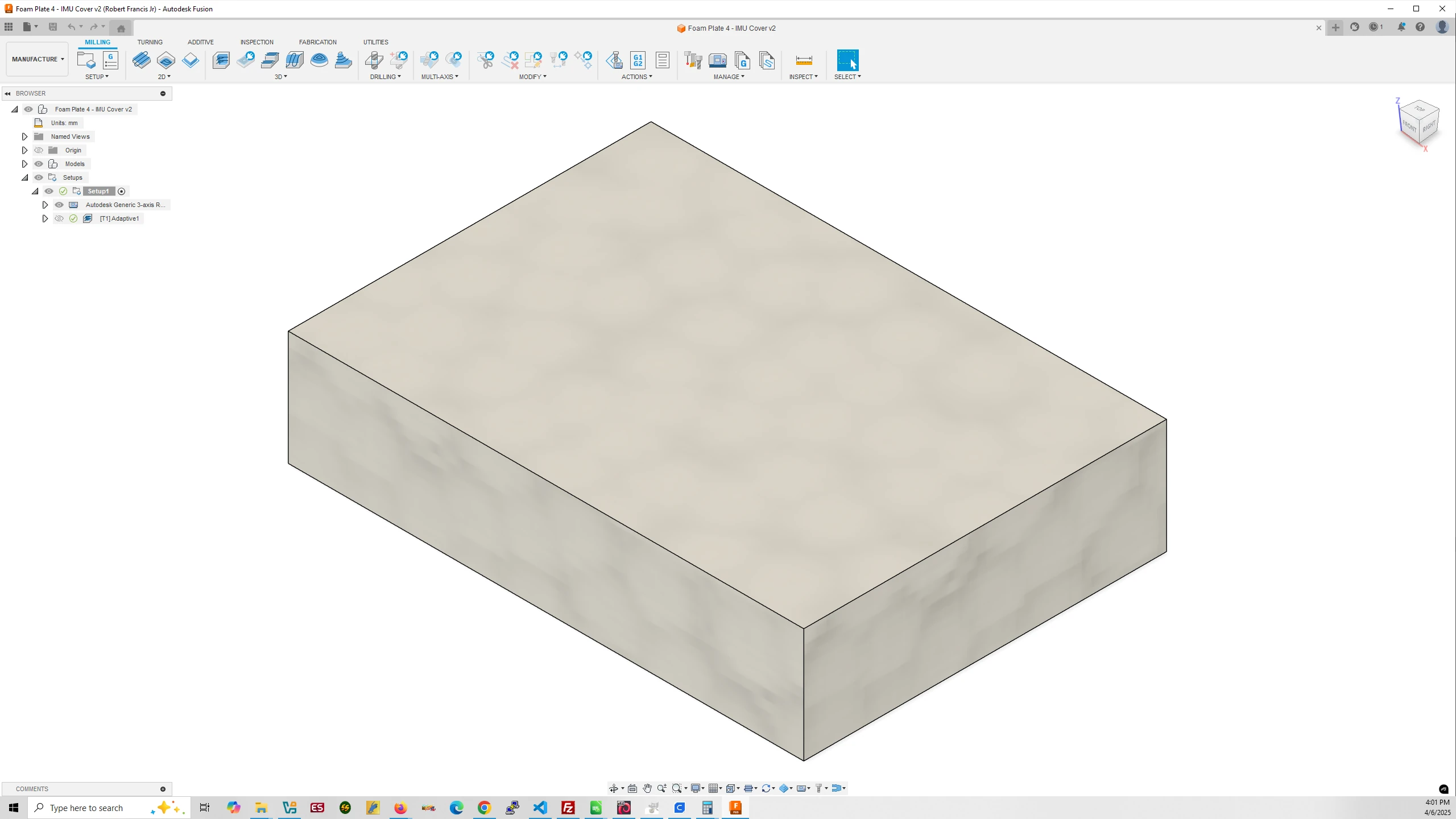
Foam Plate #4 IMU Cover
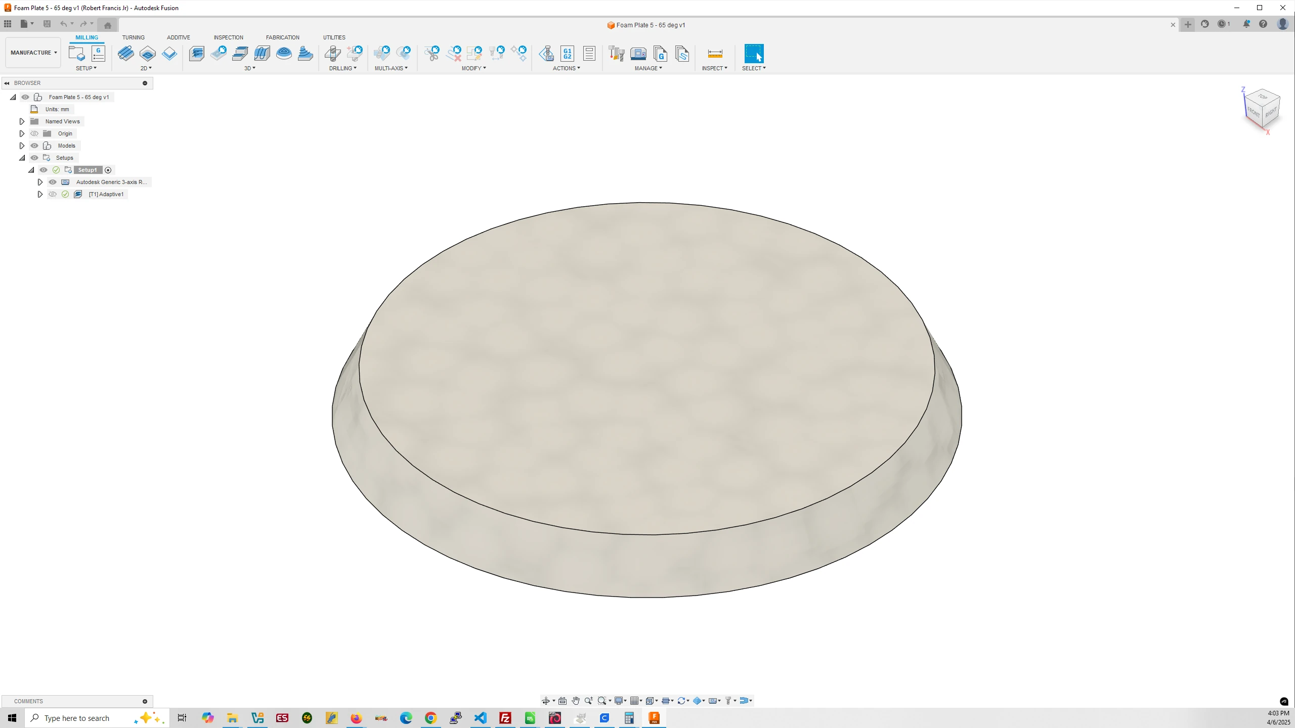
Foam Plate #5
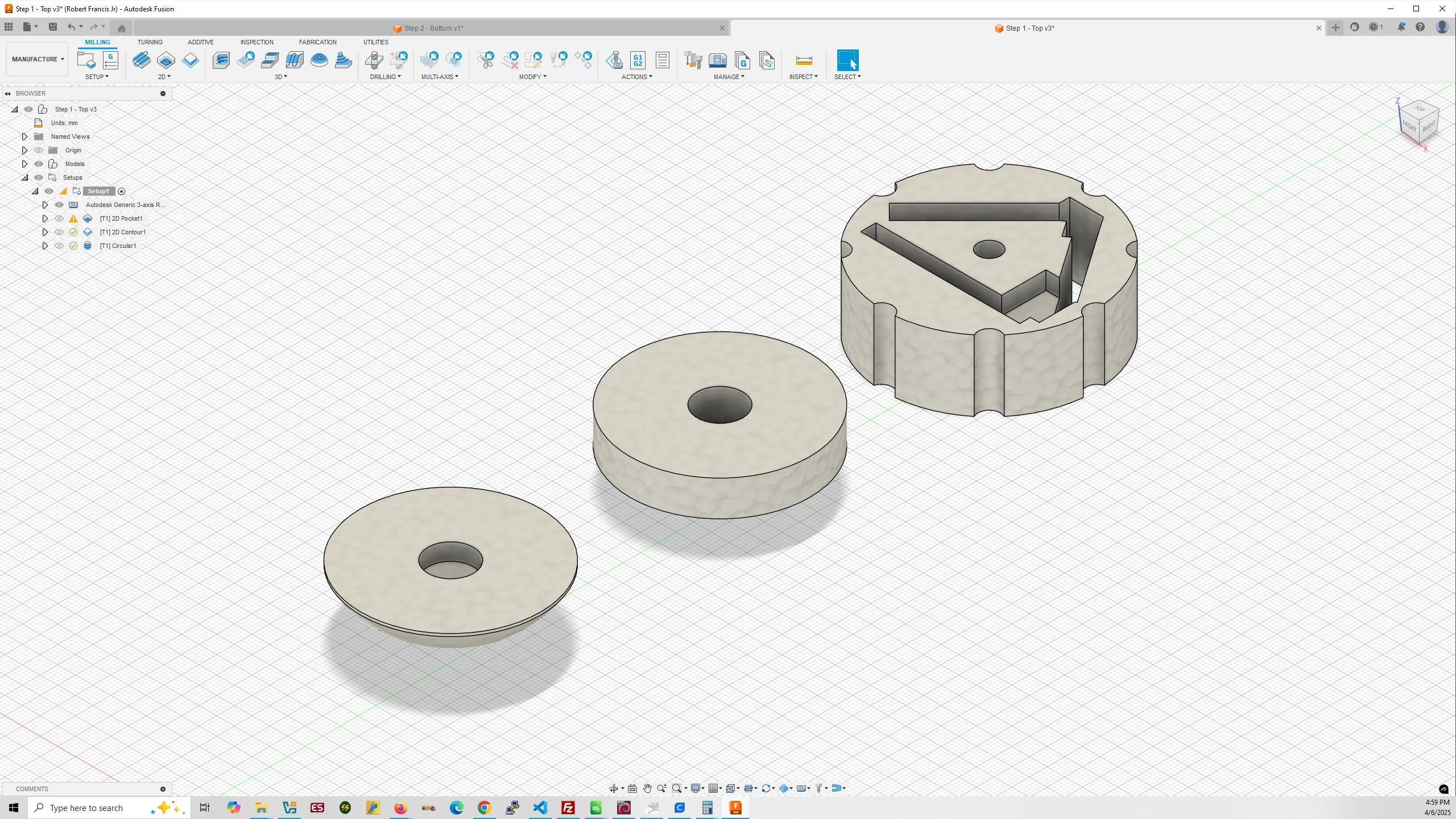
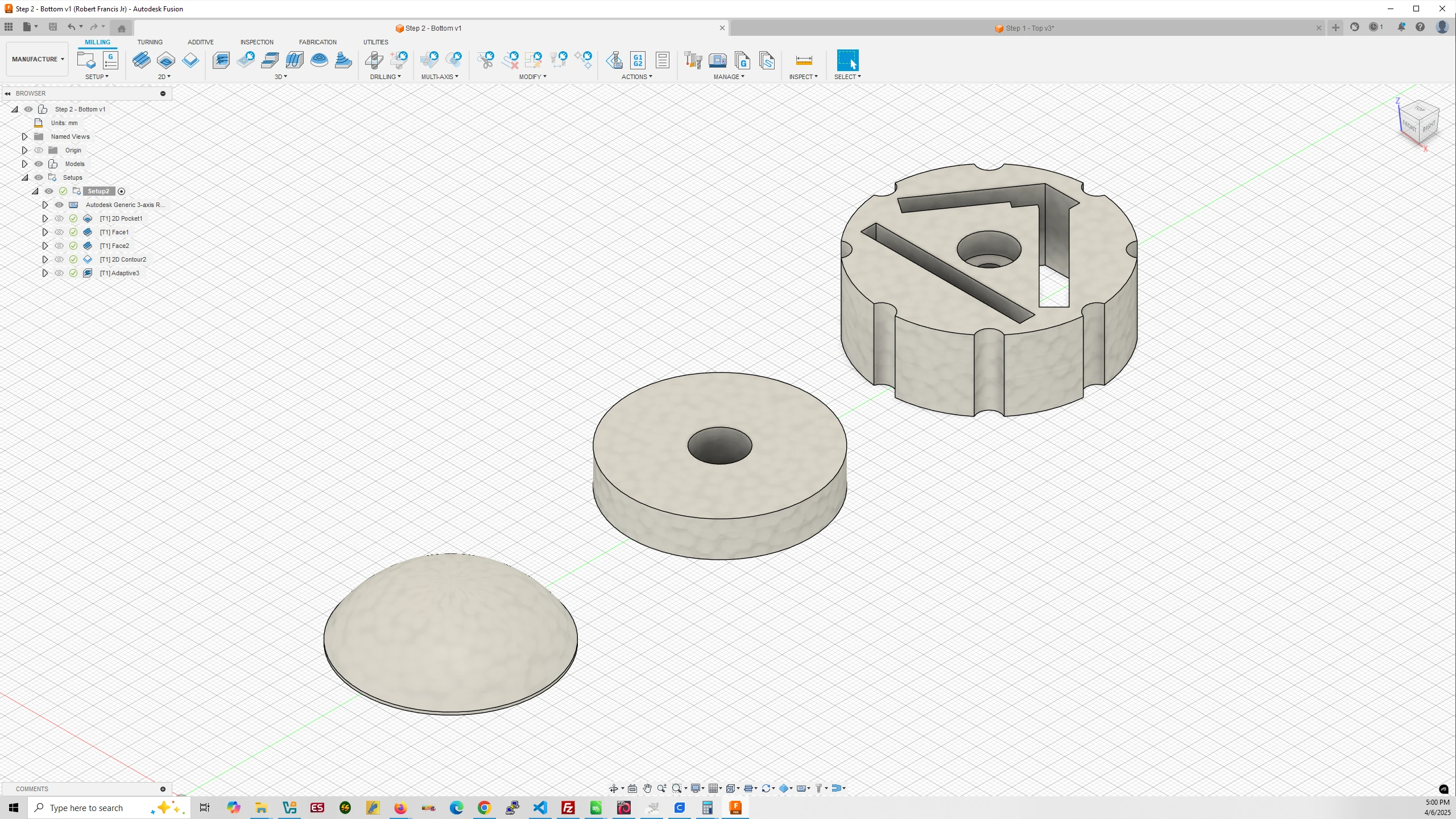
Step 1 – Top (Place New Foam Strip in Router)
- Pocket milled in Foam Plate 1 and 3.
- 2D Contour mills material in Foam Plate 3.
- Circular cuts holes in Foam Plate 2 and 3.
Step 2 – Bottom (Flip Over the Foam Strip)
- Pocket milled in Foam Plate 3.
- Facing milled on Foam Plate 2 and 3.
- 2D Counter cuts out Foam Plate 2 and 3.
- 3D Adaptive Clearing mills away material on Foam Plate 1.
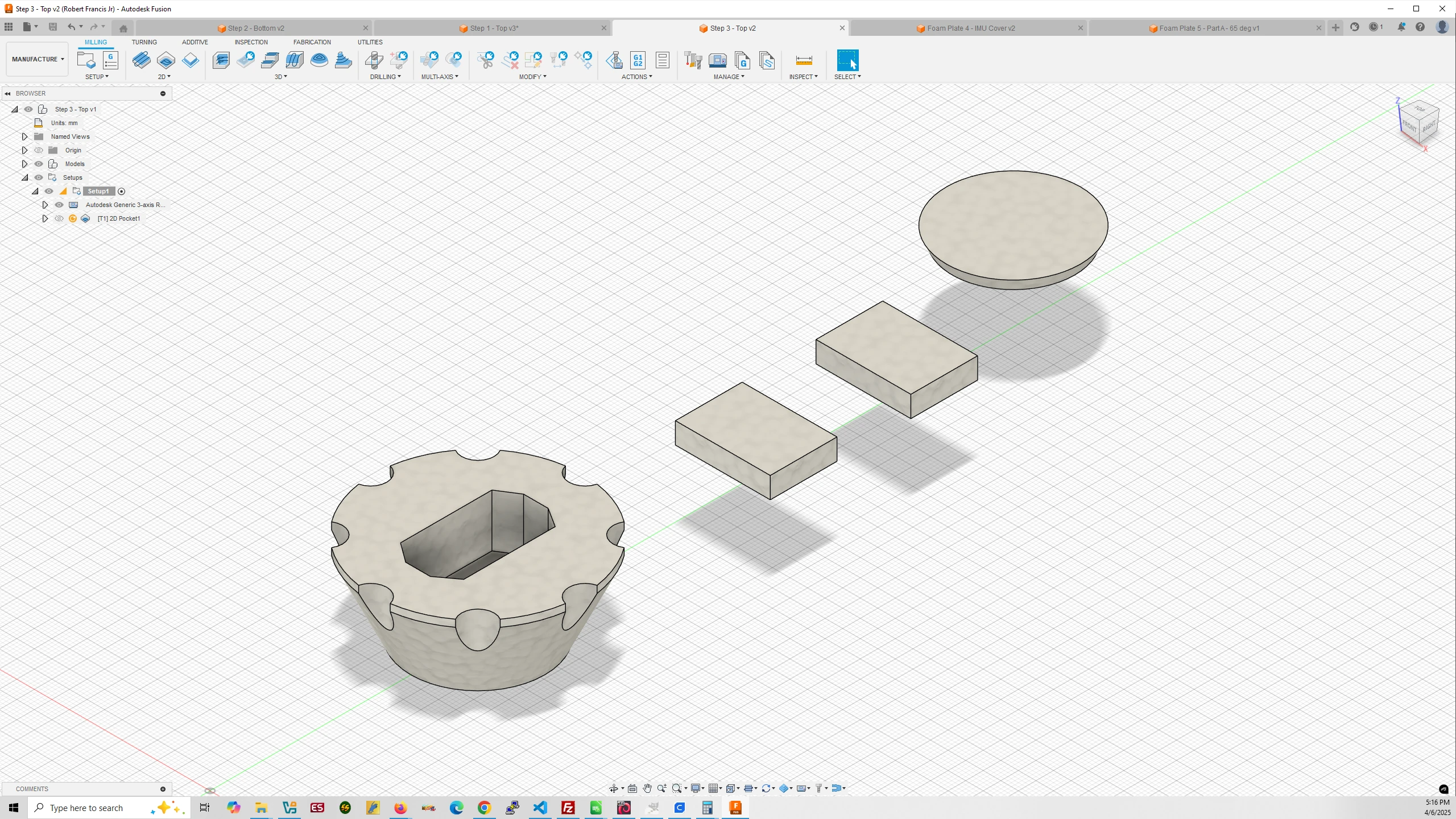
Step 3 – Top (Place New Foam Strip in Router)
- Pocket milled in Foam Plate 4
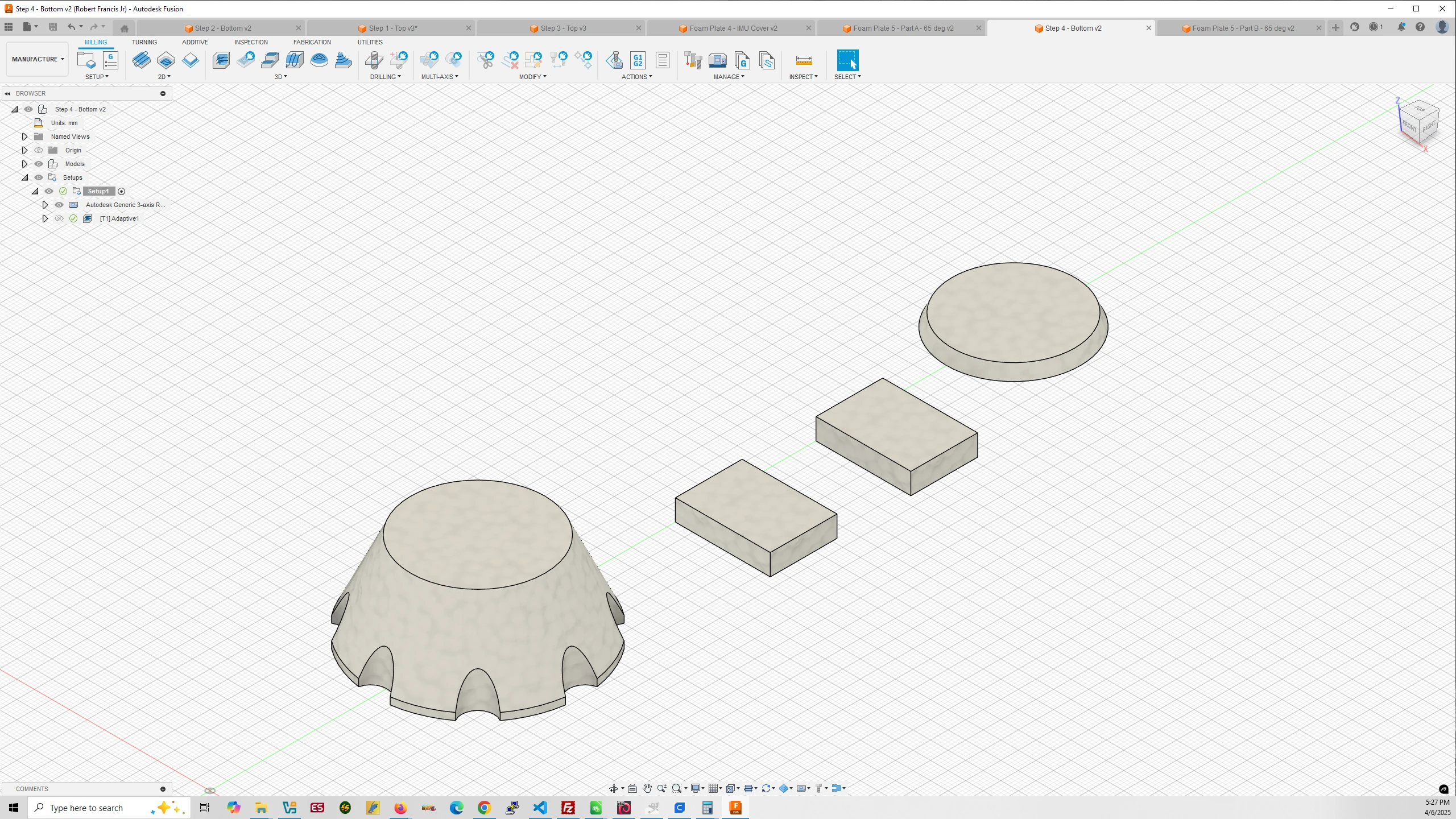
Step 4 – Bottom (Flip Over the Foam Strip)
- 3D Adaptive Clearing mills Foam Plate 4, IMU Covers, and Foam Plate 5.
Step 1 – Top
Step 2 – Bottom
Step 3 – Top
Step 4 – Bottom
7. Configure the Free-Fall Object’s Electronics
7.a. Install the Arduino IDE and Required Boards and Libraries
In order to upload programs from your PC to the Arduinos you will be using you need to install some software from Arduino. Click the link to my Arduino Configuration and Setup guide for links and instructions.
7.b. Calibrate Your IMUs
Even if you do not plan to use the BMI270 IMU onboard your Arduino Nano 33 BLE Rev2 without headers that will be used in the free-fall object I would encourage you to calibrate it before soldering wires to it.
For calibration of your other IMUs I would recommend plugging in the Arduino Nano 33 BLE Rev2 with headers used in the drop-device, into a breadboard, plugging in the STEMMA QT male pins into the pins in the breadboard aligned with the appropriate pins in the Rev2.
Arduino Nano 33 BLE Rev2
STEMMA QT Cable
This will prevent any initial wear and tear on the STEMMA QT cable wire connections that will be soldered to your headerless Rev2 as well as the wire connections that will be soldered to the PowerBoost board.
Here is a link to the Calibration Device I have created with all the needed design files for printing and instructions for assembly. You will also find Arduino calibration code for five IMUs on this page and instructions. I recommend choosing two IMUs from the supported IMUs and I would recommend against using the BMI270 as it is the slowest and least accurate.
7.c. Upload the Free-Fall Object Code to the Arduino
The headerless Arduino Nano 33 BLE Rev2 needs the Free-Fall Object code uploaded to it for experimental runs.
Download FreeFallObjectFinal Arduino Code
I have written code for the Arduino that begins recording IMU accelerometer and gyroscopic data after the green release button is hit on the drop device and the free-fall object is released by the drop-device’s solenoid coil. After the object passes through the IR beam sensors at the bottom of the drop device the IMU data along with fused data generated by a Mahony filter transfers to the Arduino Nano 33 BLE Rev2 in the drop-device and is recorded to an attached microSD card.
Important – At the top of the Free-Fall Object code there are five booleans:
bool useBmi270 = false;
bool useIcm20649 = false;
bool useIcm20948 = false;
bool useIsm330dhcx = false;
bool useLsm6dso32 = false;
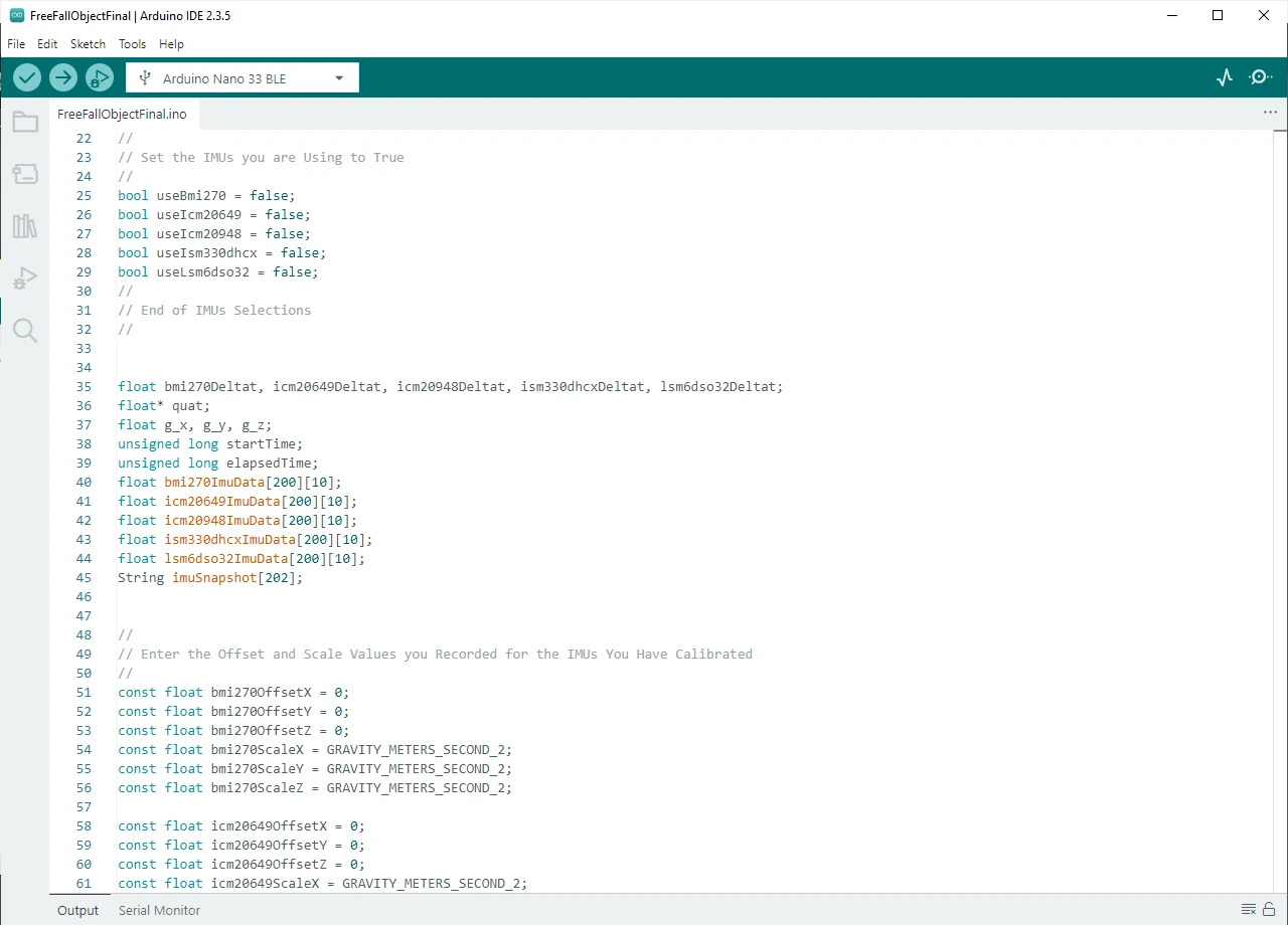
For the IMUs you are using in your experiment you need to set the corresponding booleans to true instead of false.
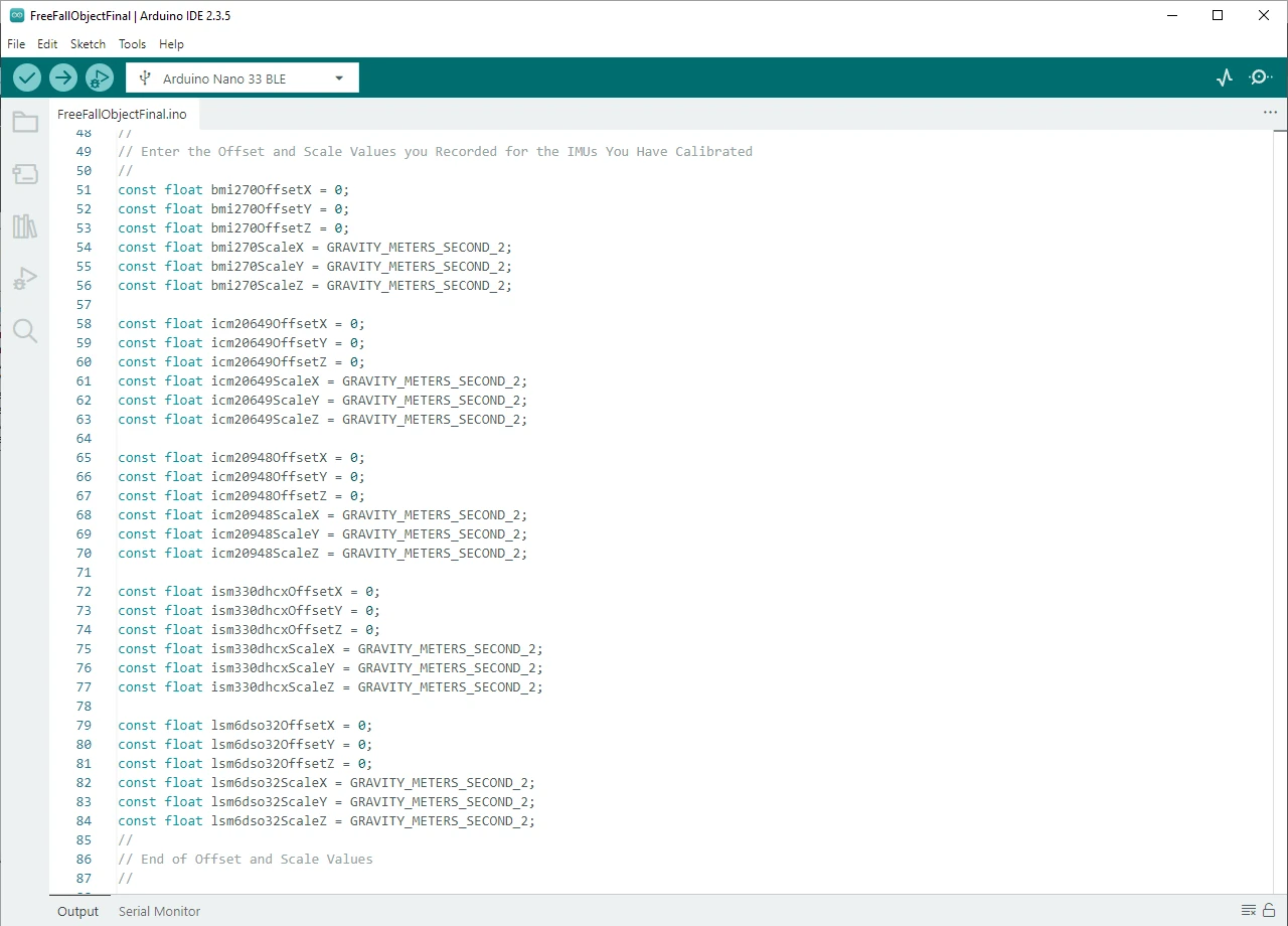
You also need to add the Offsets and Scaling values you recorded when you performed your IMU calibrations.
7.d. Solder the Arduino Nano to the PowerBoost 500
How to solder is beyond the scope of this guide. If you do not have a soldering and not know how to solder wires to circuit boards I recommend viewing this page to learn the tools and materials needed along with a link to a Soldering 101 guide.
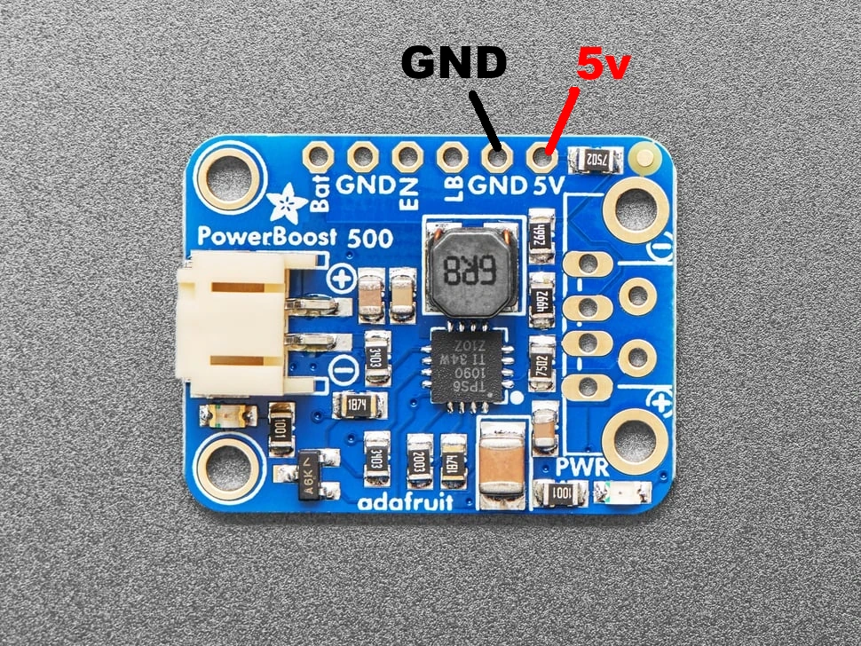
We will be using the the 24AWG wire from the materials list to connect the Arduino to the PowerBoost. I recommend using a black wire for Ground and Red wire for 5V.
As you can see in the image of Foam Plate 5 above there are parts milled all the way through the foam. Those are to hold the Arduino, the PowerBoost, and a Lipo battery that plugs into the PowerBoost. The small pocket not milled all the way through is where the wires between the Arduino and PowerBoost run connecting the two boards. The wires should be short and soldered from GND to GND and 5V to 5V.
Arduino Nano 33 BLE Rev2
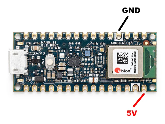
PowerBoost 500 Basic
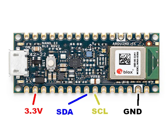
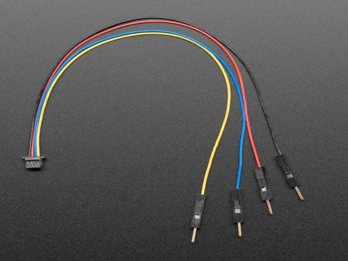
7.e. Solder the Arduino Nano to the STEMMA QT Cable
The quick connector plugs into the Adafruit BNO055. You will need to cut the breadboard wire ends off, strip the insulation with a wire stripper and solder the wires to the Arduino Nano pins identified in the image below. The colors of the wires match up to the colors used in the Arduino Nano image.
Arduino Nano 33 BLE Rev2
STEMMA QT Cable
Now, when you begin free-fall tests you will attach the Lipo Battery to the PowerBoost 500 and tuck the Arduino, the PowerBoost, and the Lipo battery into Foam Plate 3. The Lipo battery and PowerBoost will provide electricity to the Arduino and IMUs and the Arduino’s onboard Bluetooth device will relay the IMU data from the attached IMUs tucked into Foam Plate 4 to the drop-device’s main Arduino where it is recorded on a microSD card.
Make sure to fully charge the Lipo battery with the USB charger before use. A green light should come on on the charger when the Lipo battery is charged.
8. Manufacture Drop-Device Components
The drop-device is designed to fit in a room with 8ft or higher ceilings. If your ceilings are lower than 8ft you will need to make the two long 2x4s shorter.
8.a. Drill Hole Templates
Download Drop-Device Drill Hole Templates
The drill hole templates will be used for drilling precise holes in the ends of the 2×4 legs, in the legs to attach the braces, into the feet to attach adjustable pegs, and to mount the IR sensors on the legs.
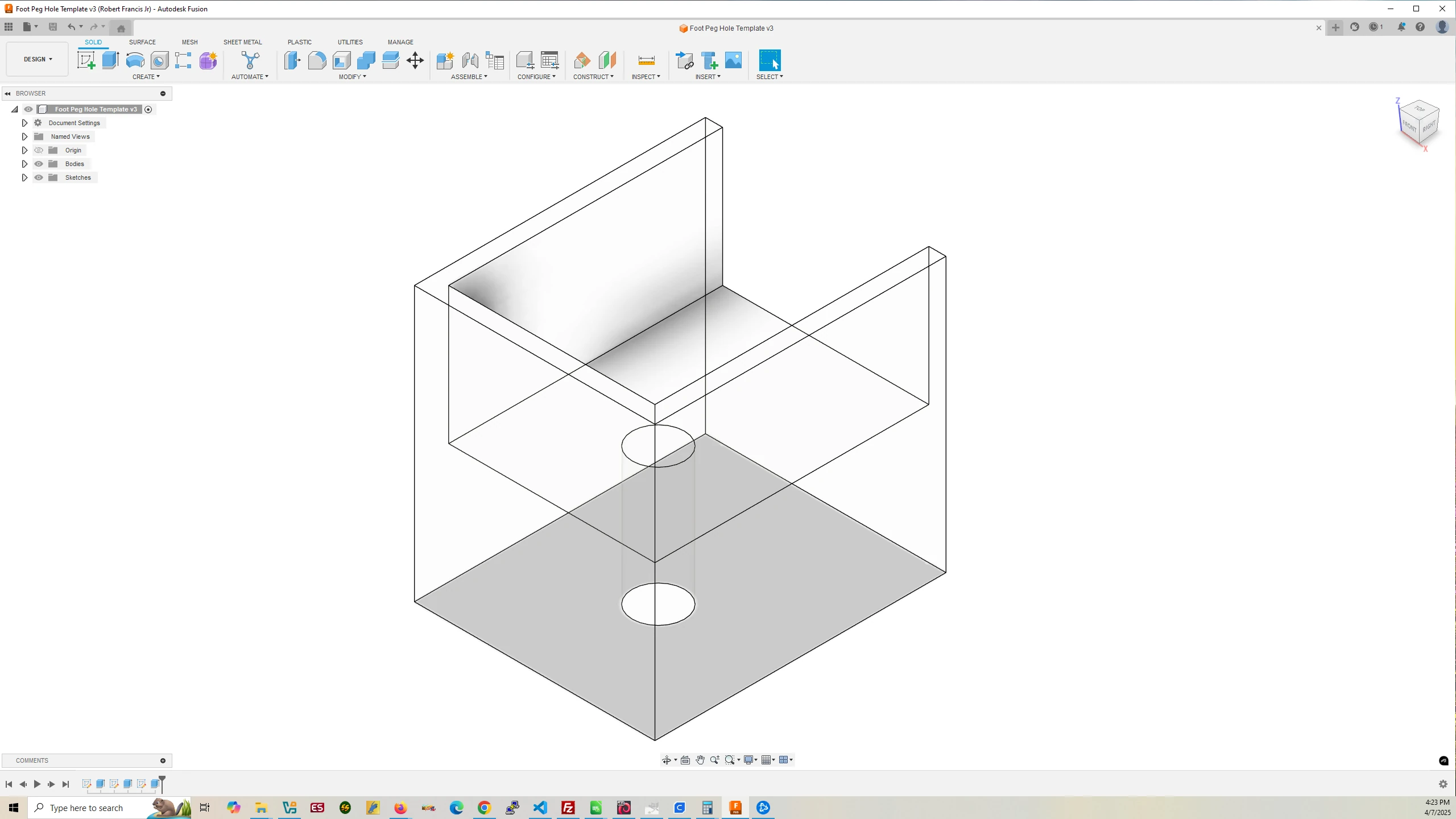
Foot Peg
Drill Hole Template
Filament Used: 36g – 11.94m
Time to Print: 1 hours 55 minutes
- Ultimaker Cura Settings
-
- Walls > Wall Thickness > 2.0 mm
- Infill > Infill Density > 5.0%
- Support > Generate Support > None
- Build Plate Adhesion > Skirt
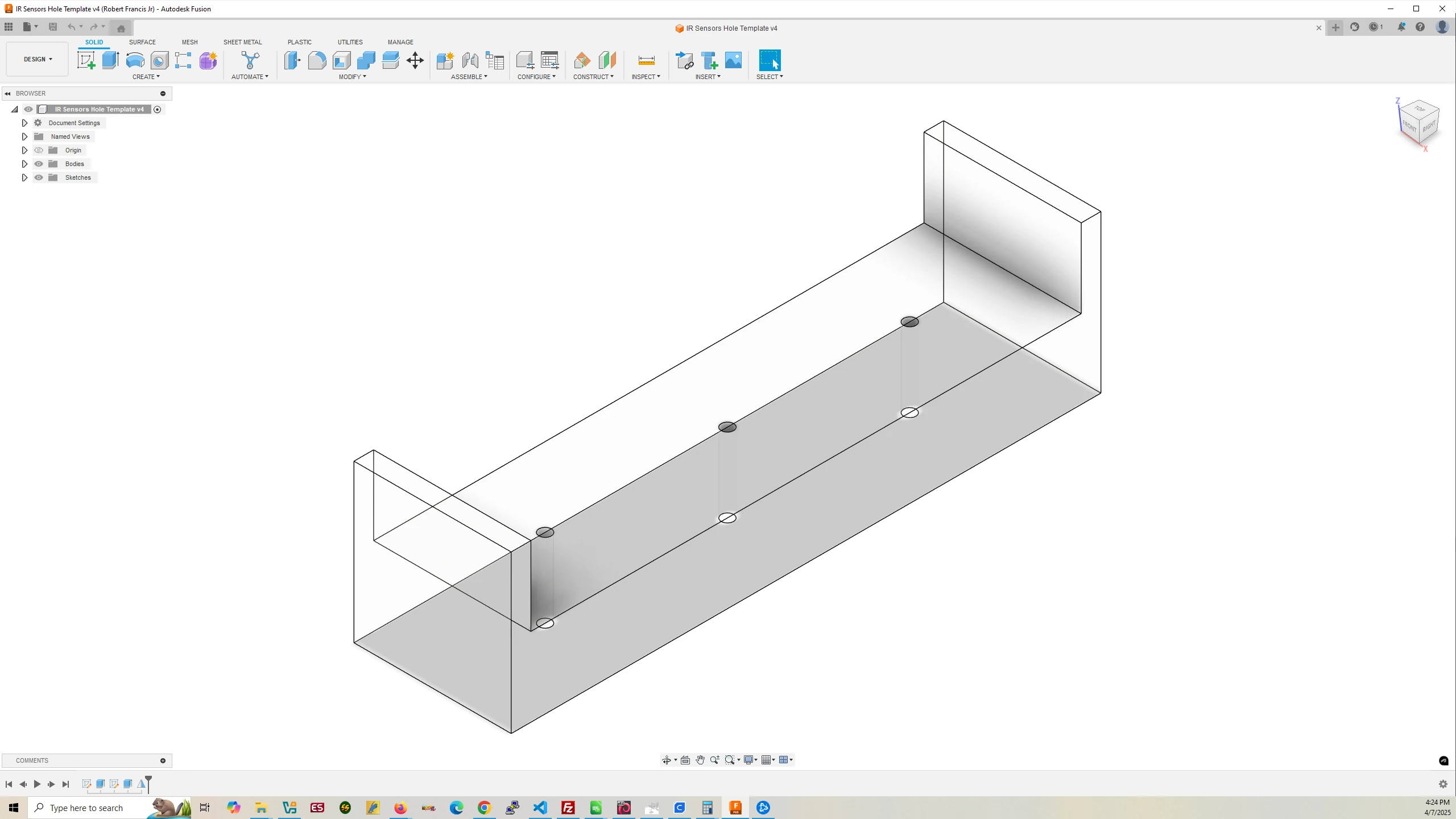
IR Sensor
Drill Hole Template
Filament Used: 16g – 5.43m
Time to Print: 1 hours 5 minutes
- Ultimaker Cura Settings
-
- Walls > Wall Thickness > 2.0 mm
- Infill > Infill Density > 5.0%
- Support > Generate Support > None
- Build Plate Adhesion > Skirt
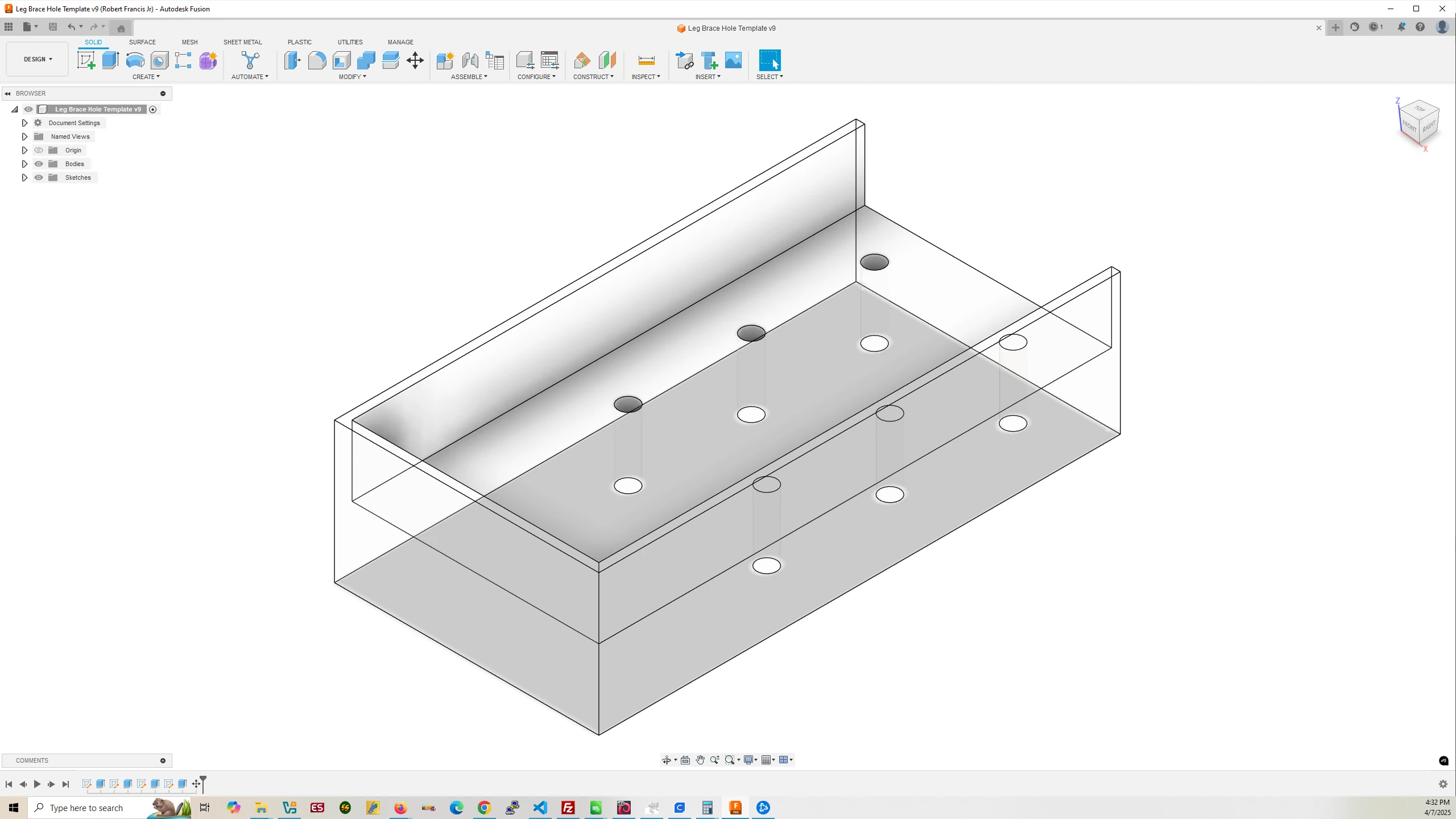
Leg Brace
Drill Hole Template
Filament Used: 149g – 50.08m
Time to Print: 6 hours 49 minutes
- Ultimaker Cura Settings
-
- Walls > Wall Thickness > 2.0 mm
- Infill > Infill Density > 5.0%
- Support > Generate Support > None
- Build Plate Adhesion > Skirt
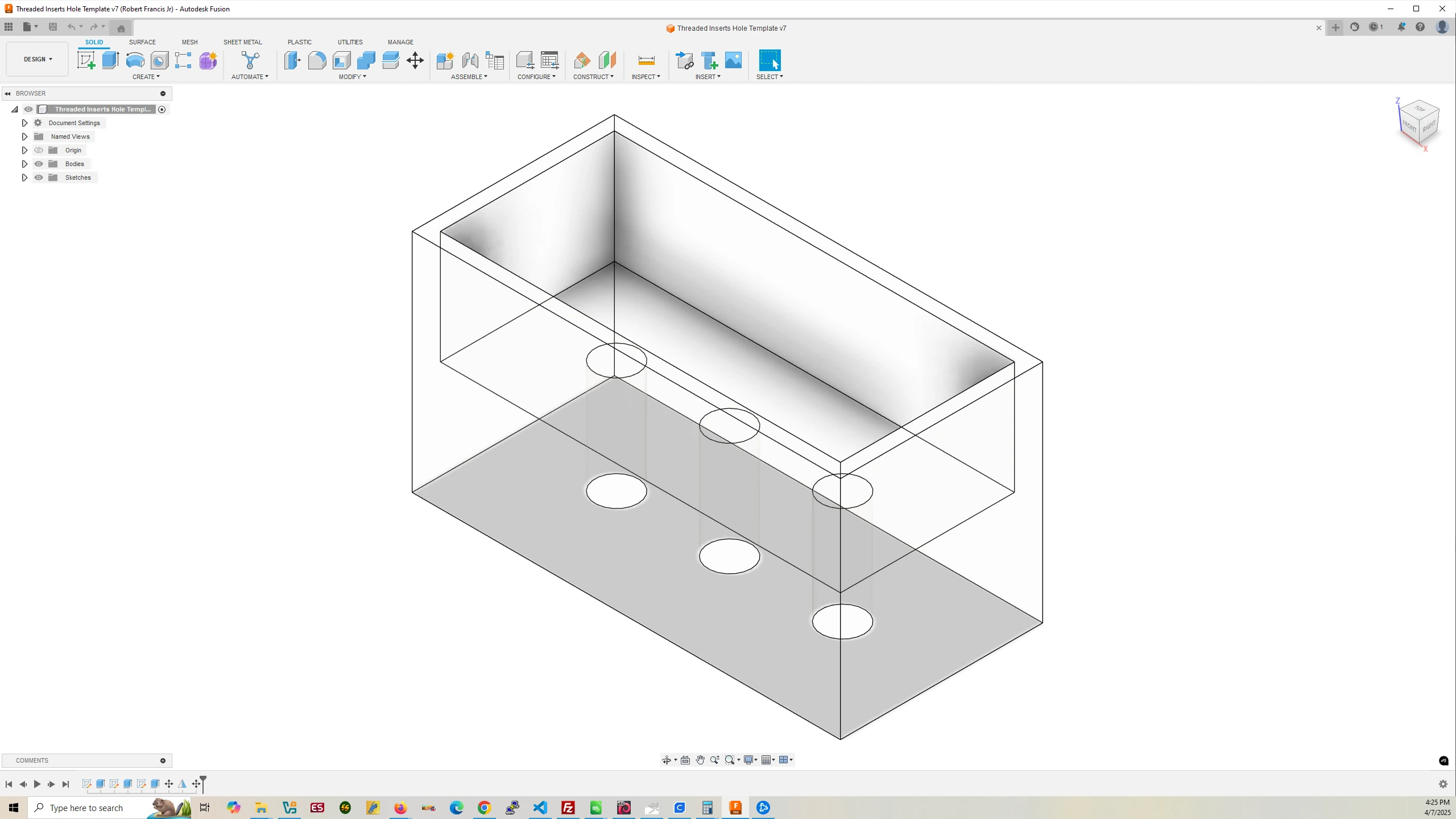
Leg Threaded Inserts
Drill Hole Template
Filament Used: 64g – 21.30m
Time to Print: 3 hours 17 minutes
- Ultimaker Cura Settings
-
- Walls > Wall Thickness > 2.0 mm
- Infill > Infill Density > 5.0%
- Support > Generate Support > None
- Build Plate Adhesion > Skirt
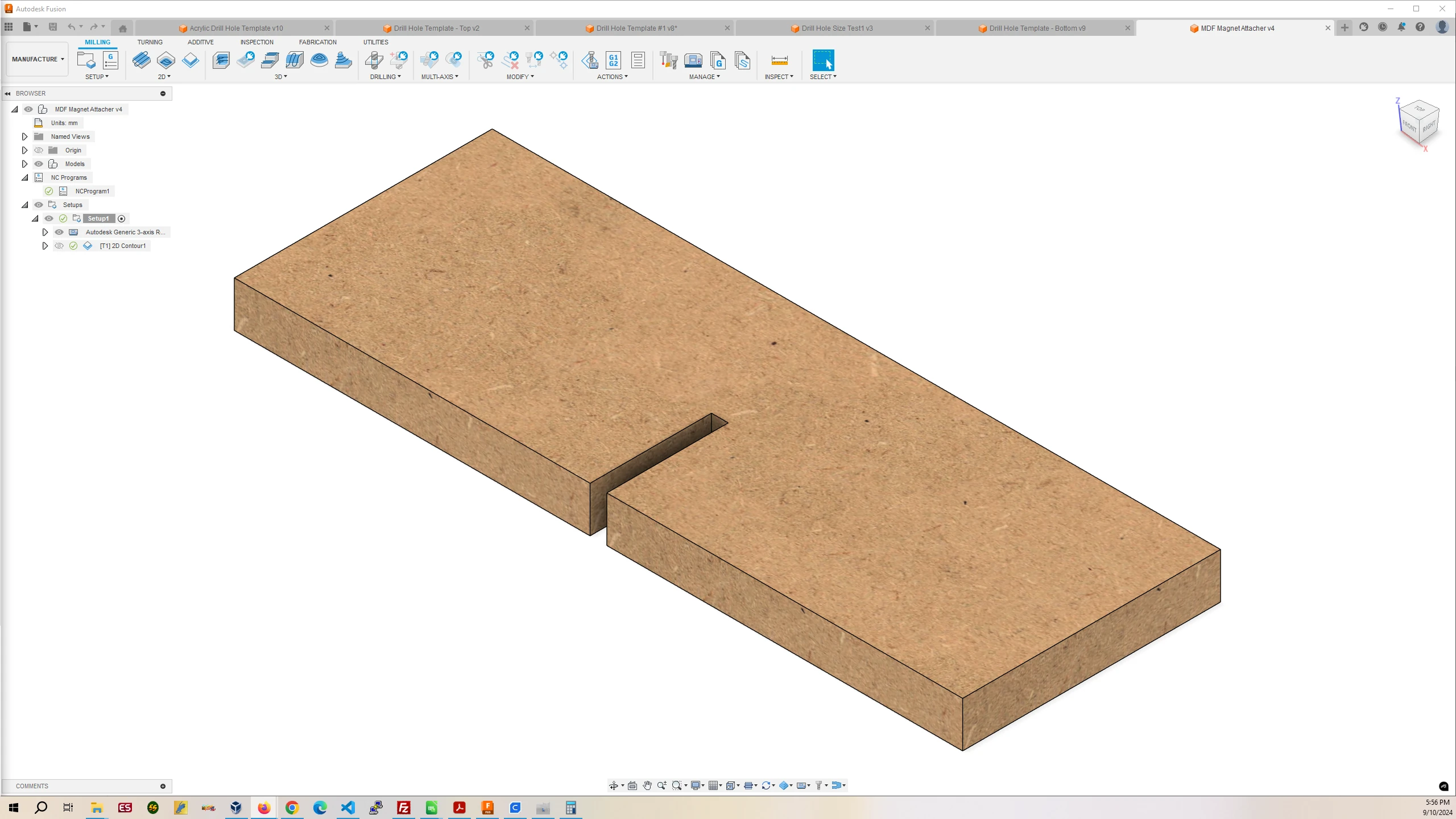
8.b. Cut and Mill 2x4s and MDF and Assemble
Download 2×4 and MDF Cutting and Milling Files
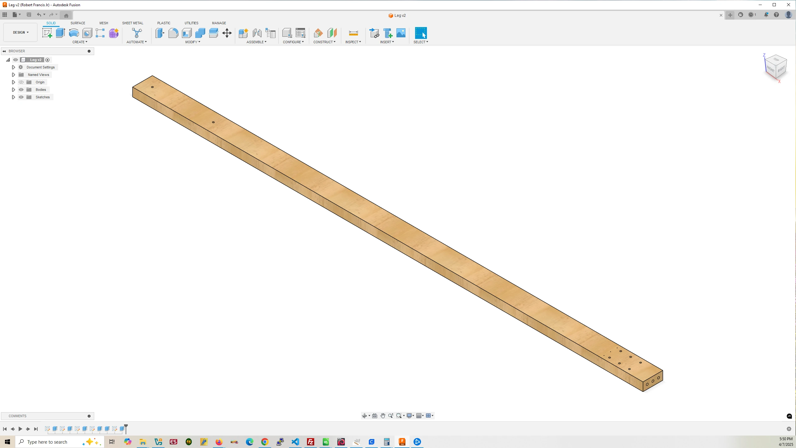
Leg
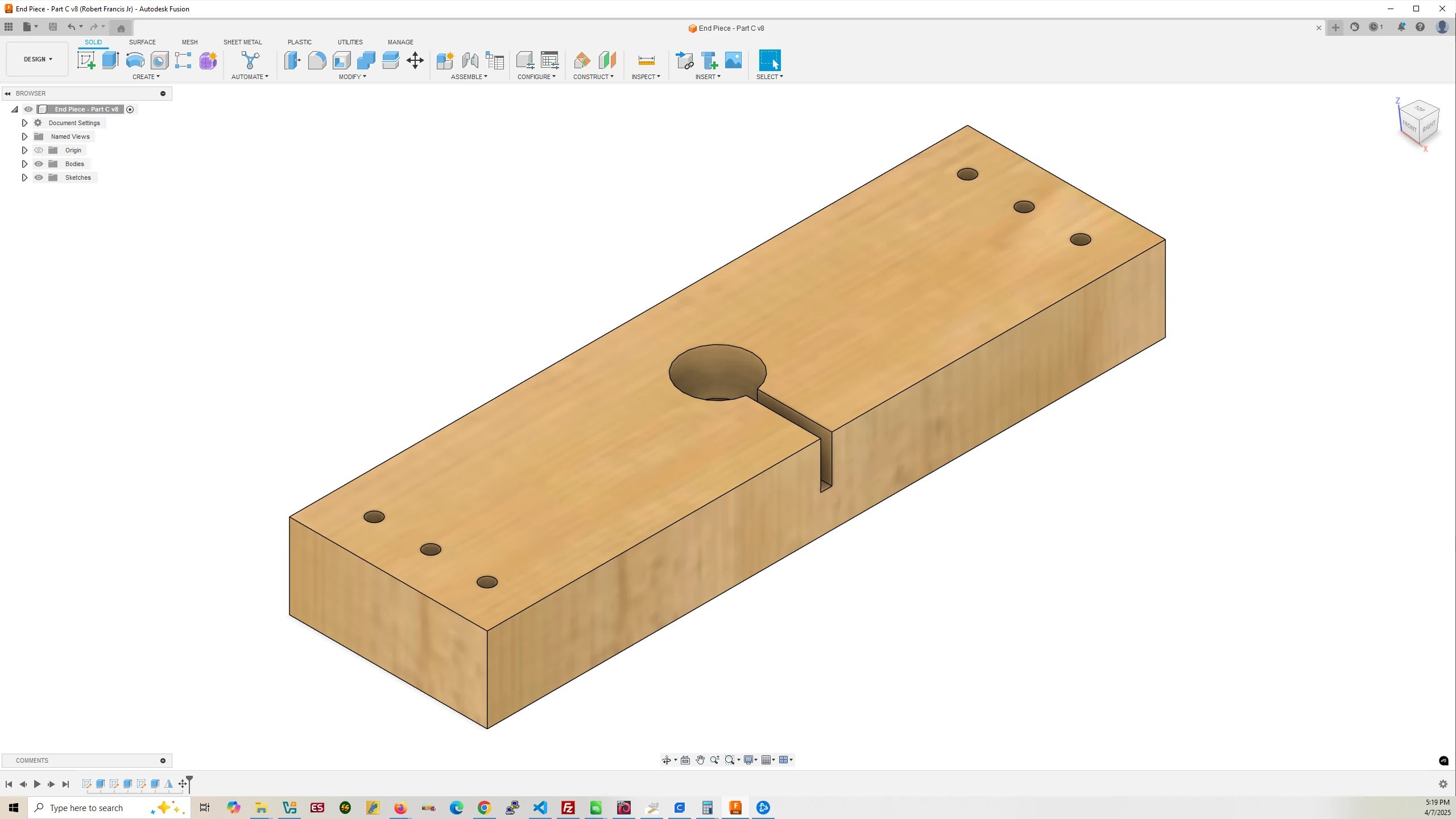
End Piece – Top
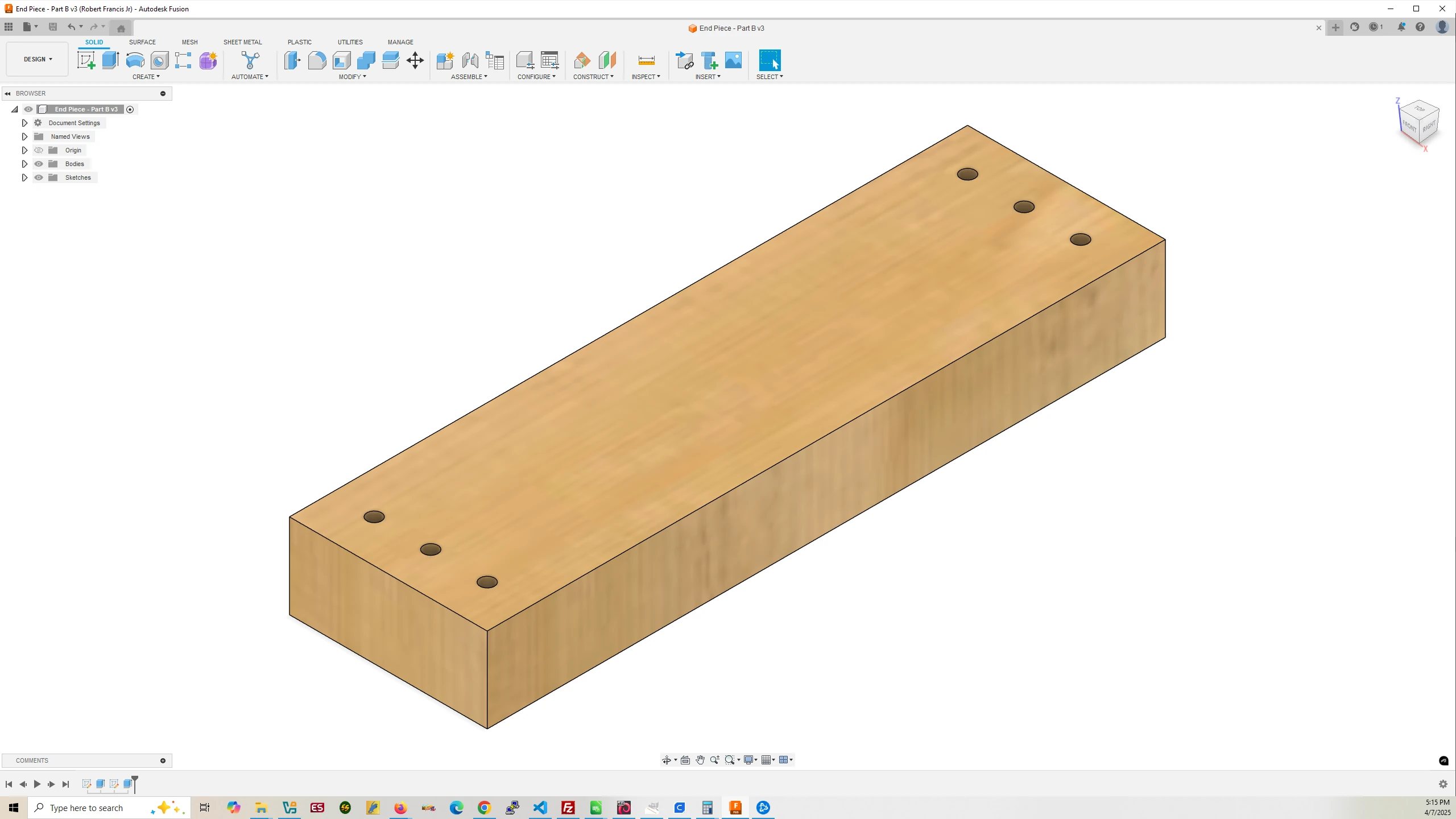
End Piece – Bottom
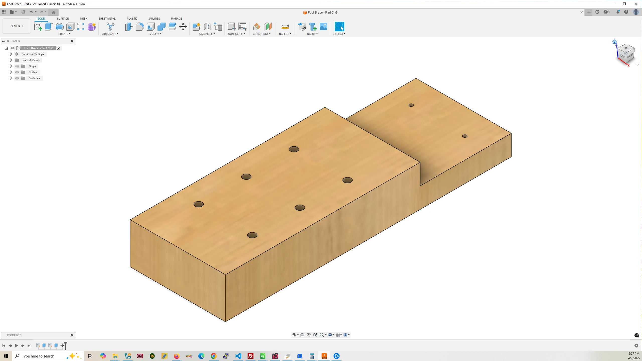
Foot Brace

Foot
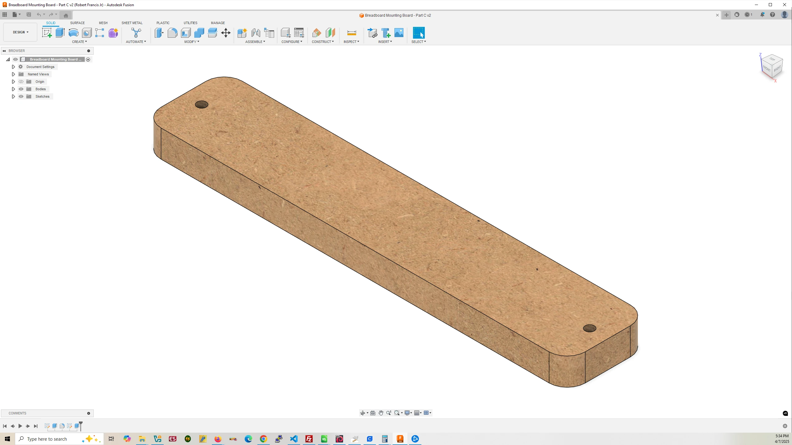
Removable MDF Breadboard Mounting Board
Step 1 – End Pieces
- Insert a 1/8″ milling bit in your CNC router.
- Cut two pieces of 2×4 slightly larger than 12″ (304.8mm).
- File: End Piece – Part A – Cuts the 2×4 to 304.8mm.
- File: End Piece – Part B – Drills holes for six 1/4″-20 bolts.
- File: End Piece – Part C – Only one End Piece should Part C – Mills a pocket and slot for the solenoid coil and drills a hole to attach the solenoid coil via a screw.
Step 2 – Foot Braces
- Insert a 1/8″ milling bit in your CNC router.
- Cut two pieces of 2×4 slightly larger than 10.5″ (266.7mm).
- File: Foot Brace – Part A – Cuts the 2×4 to 266.7mm.
- File: Foot Brace – Part B – Drills holes for six 1/4″-20 bolt holes and four holes for screws.
- Insert a 1″ surfacing bit in your CNC router.
- File: Foot Brace – Part C – Mills a rectangular block from the foot brace for mating to feet.
Step 3 – Feet
- Insert a 1/8″ milling bit in your CNC router.
- Cut two pieces of 2×4 slightly larger than 13″ (330.2mm).
- File: Foot – Part A – Cuts the 2×4 to 330.2mm.
- File: Foot – Part B – Mills a filet in the bottom right corner of 2×4.
- Flip the 2×4 horizontally to mill a second filet on the foot.
- File: Foot – Part C – Mills a rectangular block from the foot for mating to foot brace.
Step 4 – MDF to Mount Breadboard On
- Insert a 1/8″ milling bit in your CNC router.
- File: Breadboard Mounting Board – Part A – Cuts the MDF to a width of 57.15mm.
- File: Breadboard Mounting Board – Part B – Cuts MDF to a length of 298.45mm applying a Filet to the corners of the right end of the MDF along with drilling a 1/4″ hole for mounting onto a Leg.
- Flip the MDF horizontally.
- File: Breadboard Mounting Board – Part C – Applies a filet to the right side of the MDF and drills another 1/4″ hole for mounting onto a Leg.
Step 5 – Drill Holes in Feet for Leveling Pegs
- Use the 3D printed Foot Peg Hole Template for drilling holes for 1/4″-20 threaded inserts. Pegs will screw into the threaded inserts.
Step 6 – Drill Holes in Legs for Threaded Inserts
- Mount the 3D printed Threaded Inserts Drill Hole Template onto the end of a leg and drill the three holes with a 9mm drill bit. Repeat on the other end of the leg. Repeat for the other leg.
- Screw in Threaded Inserts with Allen wrench.
Step 7 – Drill Holes for Foot Brace
- Mount the 3D printed Leg Brace Drill Hole Template onto the end of a leg and drill the six holes with a 6.5mm drill bit. Repeat for the other leg.
Step 8 – Attach End Pieces to Legs
- Attach the bottom End Piece to the End of the Legs with the Foot Brace bolts holes and the top of the End Piece to the other end of the Legs with 1/4″-20 Stainless Steel 316 bolts.
Step 9 – Glue and Screw Foot Brace to Foot
- Apply wood glue to the milled out rectangular blocks on the foot and foot brace and screw the Foot Brace to the Foot. Repeat for the other Foot Brace and Foot. Wait a day for glue to dry.
Step 10 – Attach Foot Braces to Legs
- Using 1/4″-20 Stainless Steel 316 hex bolts, washers, and hex nuts, attach the Foot Braces to the Legs.
Step 11 – Drill Holes for IR Sensors
- Mount the 3D printed IR Sensor Drill Hole Template onto the leg, resting the bottom of the template against the top of the washers and drill the six holes with a manual drill using 1.5mm drill bit. Repeat for the other leg.
8.c. Load Arduino Code on Nano 33 BLE Rev2 and ESP32
Before assembling the electronics of the drop-device load the program DropDeviceFinal on the Rev2 Arduino and the program SmartphoneCameraControlFinal.
Download DropDeviceFinal Arduino Code
Download SmarrtphoneCameraControlFinal Arduino Code
8.d. Assemble Drop Device Electronics
Using the breadboards from the drop-device materials list, take one long and one short breadboard. Remove the sticker cover on the back of the long breadboard and stick breadboard to the MDF mounting board. Do the same with the short breadboard sticking it right below the long one.
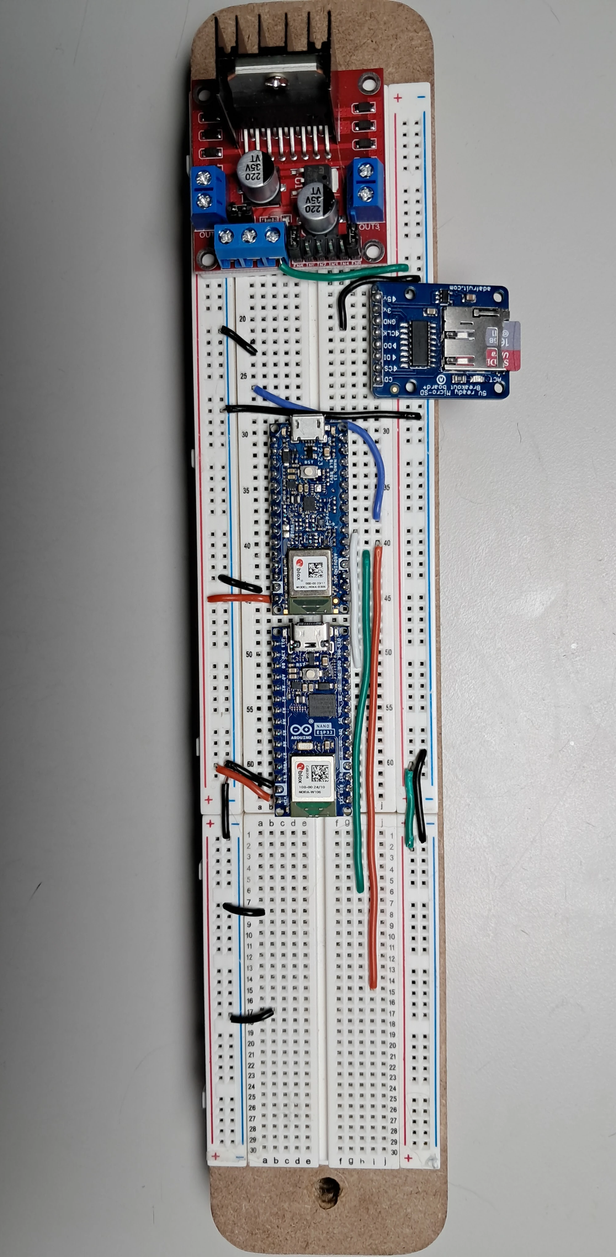
Here is an image of the electronics assembled on the breadboards.
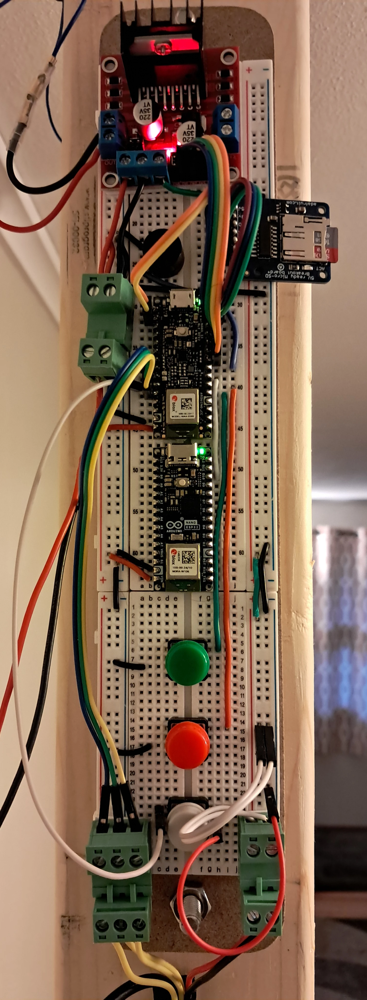
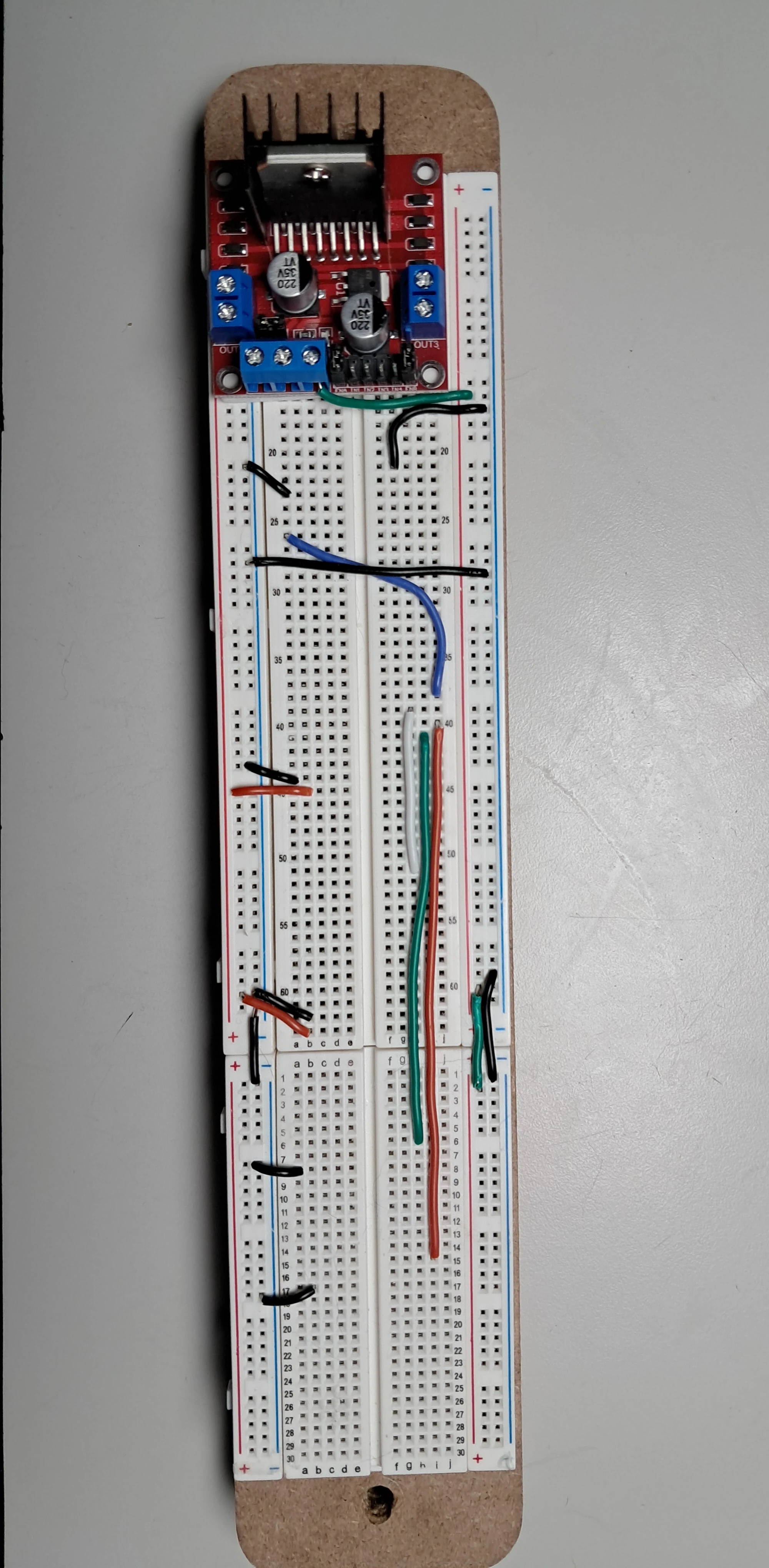
Step 1 – Attach the L298N Driver Board and Wires
- Take the double sided foam tape and cut it to size to apply to the bottom of the L298N board then stick the L298N to the very top of the long breadboard.
- Use 18-20 AWG solid core wire with the same colors as in the image below copying my wiring exactly as this will make assembly of the entire device much easier. You can click on the image to view it at a larger size making it easier to see which holes the wires plug into with guidance from the numbersm on the breadboards.
Step 2 – Install the Ardunos and microSD Card Reader
- Install the microSD Card Reader ensuring the GND pin on the reader is in the same row as where the black wire is plugged in.
- Install the Arduino Nano 33 BLE Rev2 with its microUSB connector next making sure the black and red wires on the left align with the left bottom most pins of the Rev2. The pin with white on around it on the Rev2 is ground and should be in the same row where the black wire is plugged into the breadboard.
- Install the Arduino Nano ESP32 last also making sure pin with white on around it which is ground is in the same row as where the black wire is plugged in.
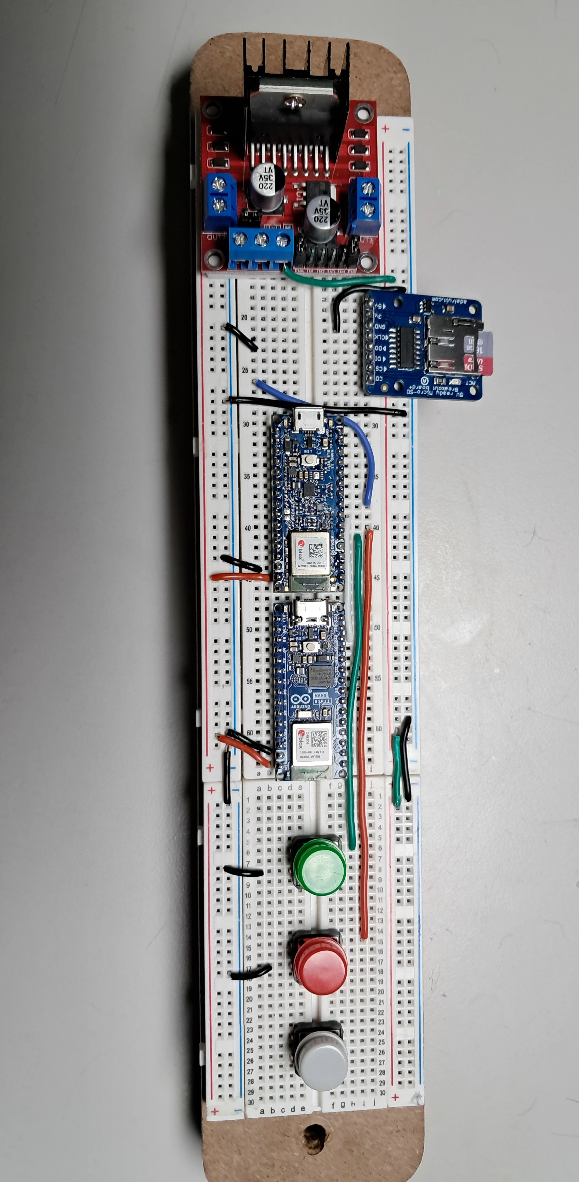
Step 3 – Install the Buttons
- Make sure the top most metal pin of the green button is in the same row as the green wire.
- Make sure the bottom most metal pin of the green button is in the same row as the black wire.
- Make sure the top most metal pin of the red button is in the same row as the red wire.
- Make sure the bottom most metal pin of the red button is in the same row as the black wire.
- The grey button is not in use normally but if debugging the device with a computer connect it to pin A5, A6, or A7 and Ground to simulate an IR beam break when the button is pressed.
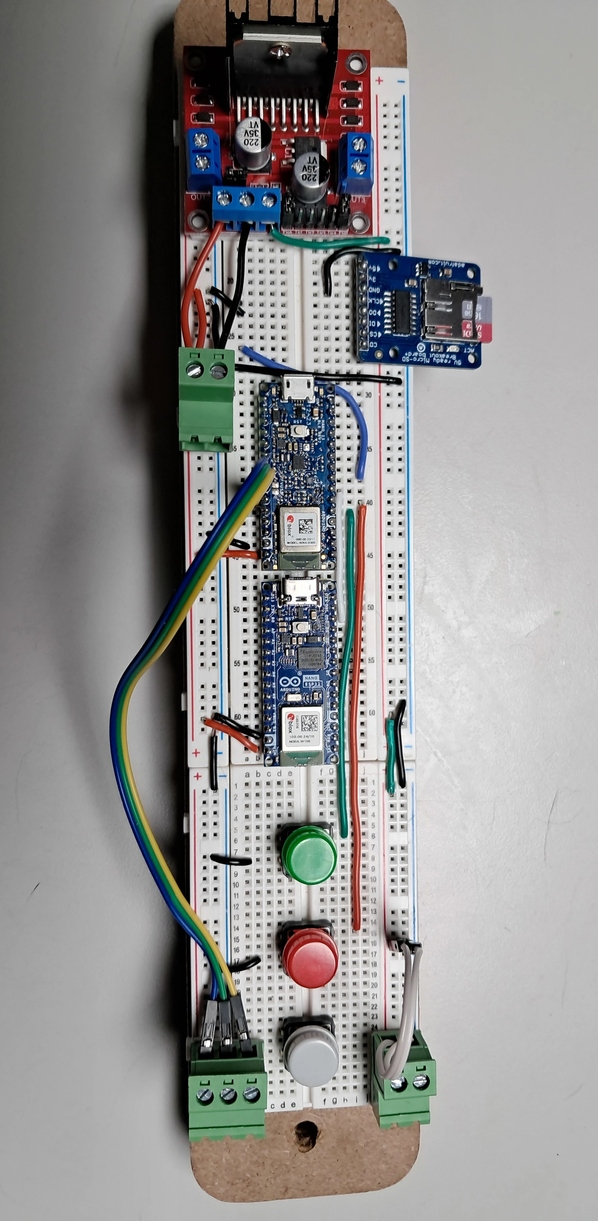
Step 4 – Install Screw Terminal Blocks
- All screw terminal blocks have double side foam tape stuck to their bottom to secure them to the breadboard.
- In the two terminal top most block connect two red solid core wires to the left terminal, one long, one short. The long one plugs into the L298N’s 12 Volt in pin and the short red wire plugs into the red positive column feeding 12 Volts to anything plugged into that column. Repeat this for the black wires, the long one connecting to the Ground in the L298N and the short one to the Ground column on the breadboard.
- The bottom left three terminal block are connected with Dupont cable to the A5, A6, and A7 pins of the Rev2 Arduino. The other side of the block not shown connect to the three IR sensors at the bottom of the drop device.
- The bottom right two terminal block are connected with Dupont cable to the 5 Volt and Ground columns of the breadboard. The left terminal to 5 Volt, the right terminal to Ground. The other side of the block not shown connect to the 5 Volt and Ground pins on the IR sensors and LEDs.
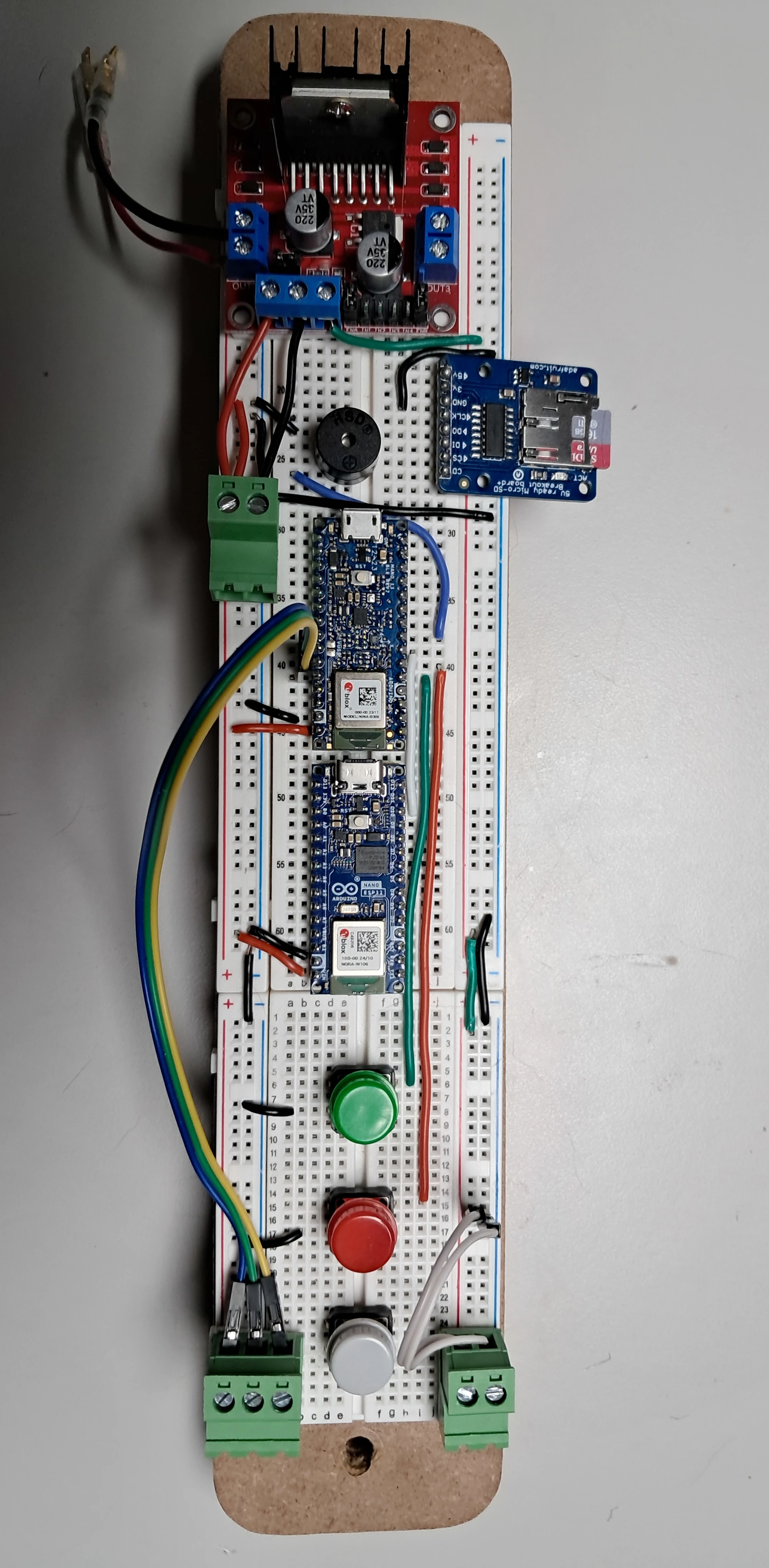
Step 5 – Install the Buzzer and L298N output wires
- The Buzzer’s long pin plugs into the same row as the blue wire. The Ground pin plugs into the same row as the black wire.
- Crimp 2.8mm small male Spade Terminals to the short red and black wires plugged into the Out1 and Out2 screw terminals. You will be crimping the female spade terminals to the Solenoid coil’s wires. By using spade terminals for the connections it is easy to flip the polarity of the solenoid coil by plugging the male spade terminals into the opposite female ones.
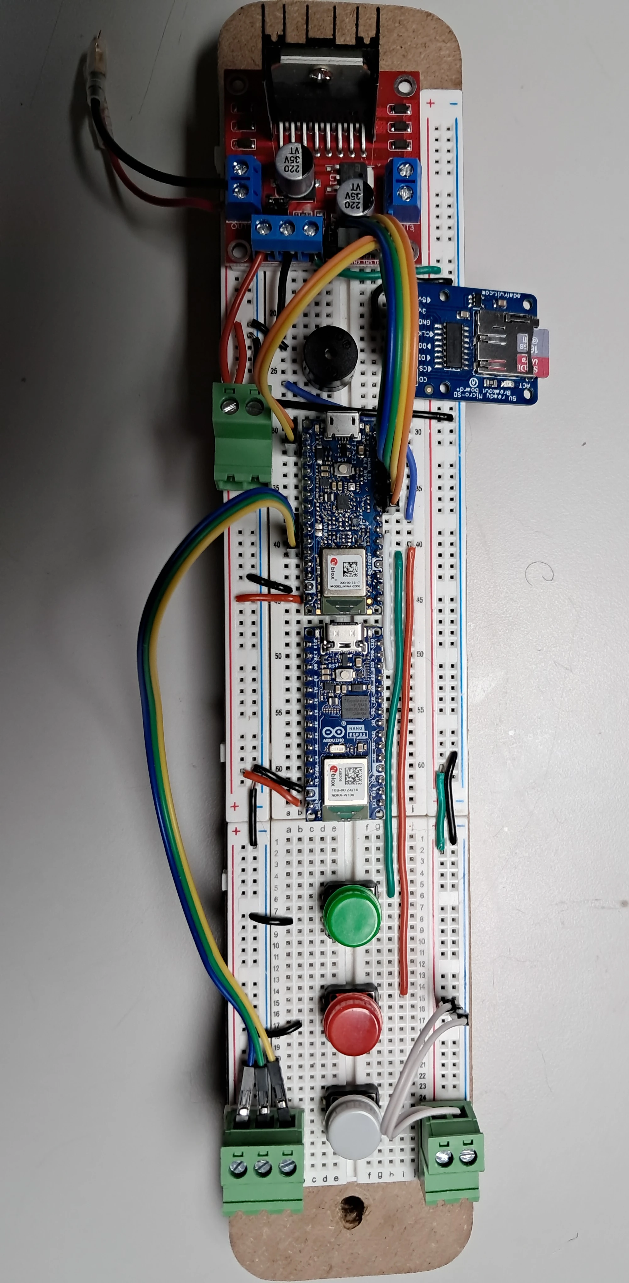
Step 6 – Install the Rest of the Dupont Cables
- Install the microSD card readers cables first. Two wires connect the 3V and CLK pins of the card reader to pin 13 and 3.3V on the Rev2 Arduino. DO connects to pin 12, DI to 11, and CS to 10 on the right side of the Rev2 Arduino.
- In1 and In2 of the L298N connect to pins 8 and 9 on the Rev2 Arduino.
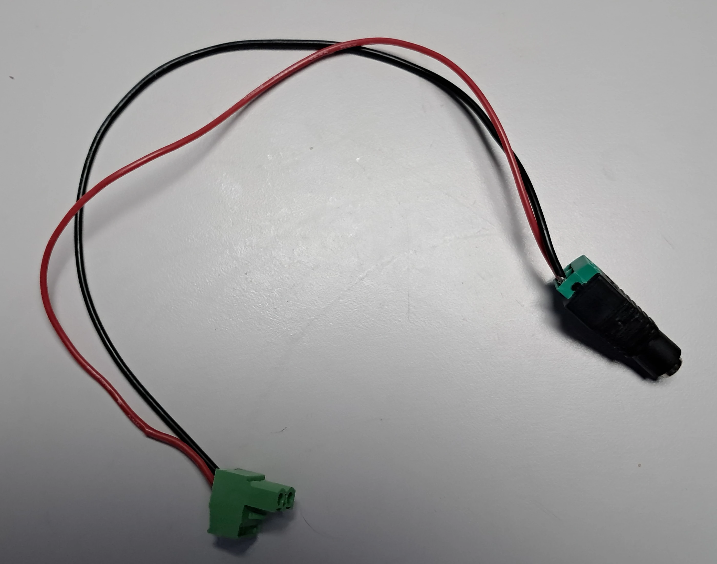
Step 7 – Assemble Main Power Connector
- Install a red wire in the (+) screw terminal, and a black wire in the (-) screw terminal in the barrel plug.
- For the two terminal screw terminal block with it plugged into the top two terminal screw terminal block on the breadboard the red wire should be on the left and the black wire on right.
- An AC adapter with a barrel plug is used to supply 12 Volt electricity to the L298N board as well as the left side of the breadboard’s electricity and ground columns with the L298N also outputting 5 Volts via the green wire to the right side of the breadboard’s electricity and ground columns.
8.e. Wiring the IR Sensors to the Arduino
The yellow wires from the IR sensors needed to be wired individually but the red 5 Volt wires and the black Ground wires can be grouped together. Below are two images of the wiring on the left and right sides of the bottom of the drop-device.
You can see that all pins of each IR sensor and LED, red, black, and yellow go into their own separate screw terminal. The output side of the red and black screw terminals uses 20 AWG stranded wire with the red and black wires being grouped together into a two terminal screw terminal. The output of these are combined with the black and red wires from the right side of the drop-device with one red and one black wire secured to a two terminal screw terminal block that plugs into the two terminal block on the bottom right side of the electronics breadboard device.
The yellow wires travel up to the three terminal block and plug into the bottom left terminal block on the electronics breadboard device.
Wiring Left Side
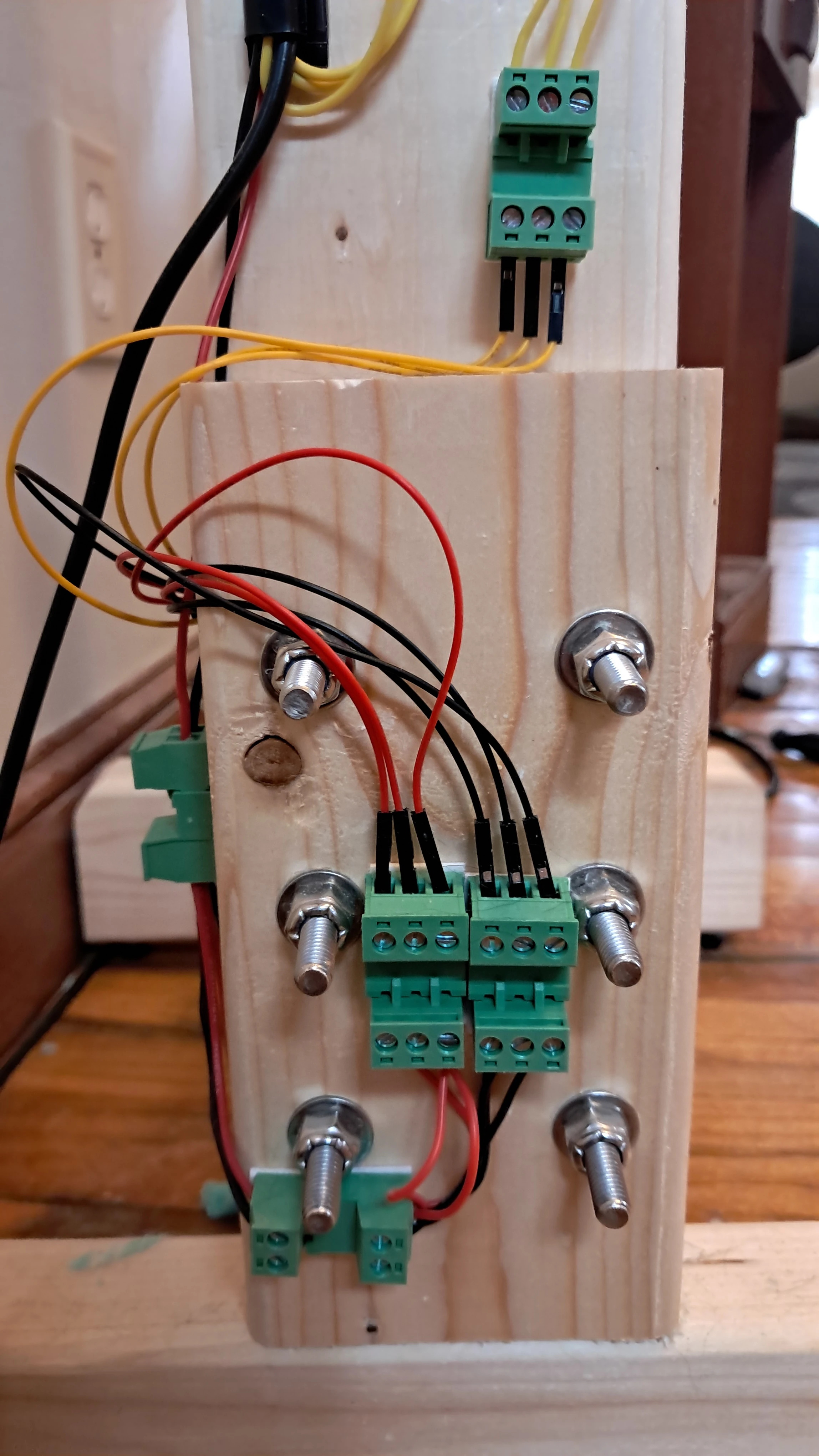
Wiring Right Side
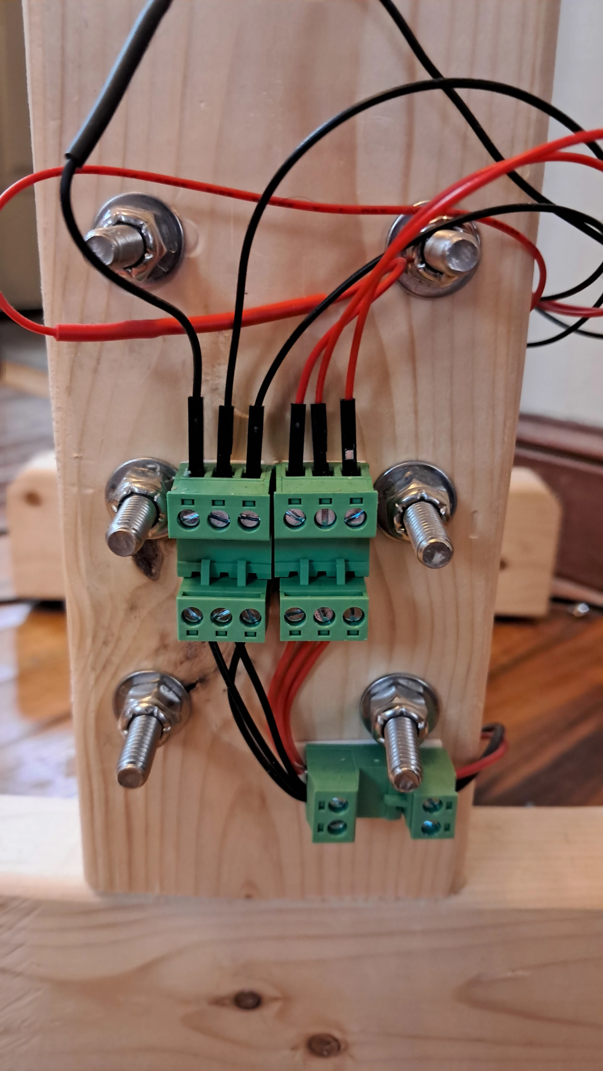
I use double sided foam tape on the bottom of the terminal blocks and adhesive cable organizer clips from the materials list to organize and hold the wires securely to the wooden frame of the drop-device.
9. Assembling the Coupled Magnets
9.a. Assembling the Attractively Coupled Magnets
I strongly urge anyone replicating this experiment to email K&J Magnetics before ordering and tell them you want them to attach the attractively coupled magnets for you.
If you try to do this yourself you run the very real risk of injury or breaking the magnets. You only need two magnets for the attractively coupled test as they don’t rely on the bolt and nut to keep them together. You simply remove the nut and bolt and flip them around to test the drop from north pole to south pole or vice versa.
With the two magnets already assembled it is merely a matter of sliding the 3.0″ Stainless Steel 316 bolt into the into the 1/4″ hole in the magnets to make for easier removal from the plastic/foam shell when the experiment is complete.
9.b. Assembling Repulsively Coupled Magnets
This is a little tricky and dangerous as the magnets will try and flip on you to couple attractively. The method I found that works is to put the Stainless Steel 316 bolt through one magnet. Use the magnet pole detector so you know which pole is on the bottom and which is on top. Then place a piece of MDF with a slot milled into it and slide it into the Stainless Steel bolt on top of the magnet.
Stand with both feet on the MDF on each side of the slot. Then you place the second magnet, make sure you know what pole is facing down with the magnet pole detector, so when you push it onto the Stainless Steel bolt there is repulsive force between the two magnets. Then simply push the magnet down far enough on the bolt and start tightening the nut. Once the nut is threaded enough on the bolt you may slide out the MDF piece.
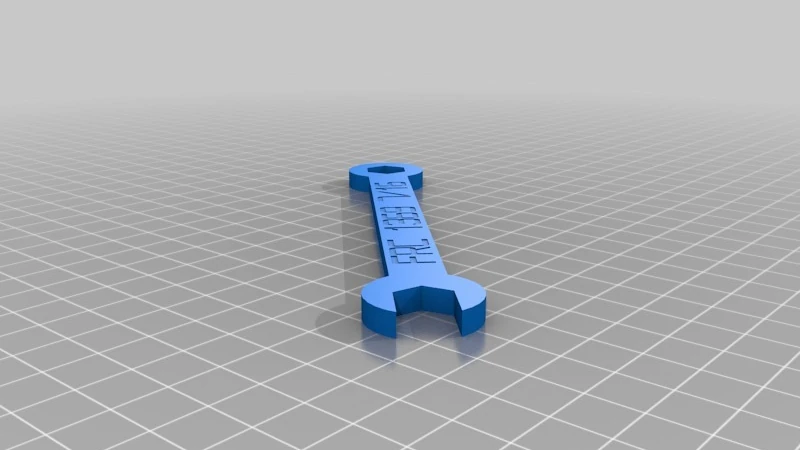
Finally, use two 3D printed plastic wrenches to hold the Stainless Steel hex bolt steady while you turn the Stainless Steel hex nut with the other wrench.
10. Assembling the Free-Fall Object
- Place Foam Piece 1 into the bottom of the Front Shell
- Insert the magnet object or control.
- Place Foam Piece 2 on top of the magnet object or control.
- Place the thin Foam Piece 5 into the Back Shell.
- Place Foam Piece 4 into the Back Shell.
- Join two IMUs with a STEMMA QT cable.
- Insert the STEMMA QT cable soldered to the Arduino into a free port on one of the IMUs.
- Tuck in the IMUs into Foam Piece 4 with the IMU Cover in between the two IMUs you are using.
- Insert the second IMU Cover into Foam Piece 4
- Plugin the Lipo battery to the PowerBoost.
- Tuck the Arduino, PowerBoost, and Lipo battery into Foam Piece 3.
- Place Foam Piece 3 into the Back Shell, half of Foam Piece 3 should be sticking out.
- Assemble Front and Back shells with M3x20mm screws.
11. Conduct Free-Fall Tests
Plug in the Drop-Device. Look at the microSD card reader. A red light should come on for a short period. If the buzzer does not make a beep the microSD card reader and card should be working properly. You can then hit the Red button. This will turn on the solenoid coil at the top of the drop-device.
It is a good idea for the solenoid coil and the side of the magnet facing it in the free-fall object to have the same polarity. This will reduce the likelihood of the magnet being pulled toward the solenoid coil which could hamper releases of the free-fall object. If they don’t have the same polarity then power off the Drop-Device and switch the two spade connectors connecting the solenoid to the L298N board on the Drop-Device.
Instructions for each trial:
- Hit the Red button
- Magnetically attach the free-fall object’s steel fender washer to the center of the solenoid coil
- Hit the Green button
- A delay of about 3 seconds will take place
- This is to allow time for your Camera in your Smartphone to turn on
- The free-fall object is released.
- The object passes through the IR beam at the bottom of the drop-device.
- The buzzer makes a sound to let you know the IR beam was tripped.
- Your camera shuts off.
- The Red light on the microSD card reader comes on and shuts off.
- Retrieve the free-fall object.
- Repeat the process from Step 1.
- After 25 drops a long beep will occur to let you know you have reached 25 trials.
- Power off the drop-device by unplugging the barrel connector.
- Remove microSD card and transfer the data to your PC.
- Transfer footage from your camera to your PC as well.
- Data analysis is beyond the scope of this tutorial. I have two Libreoffice Calc templates for this though:
Download IMU Average Acceleration Template
Download Free-Fall Object Average Acceleration Template